Inclusive design
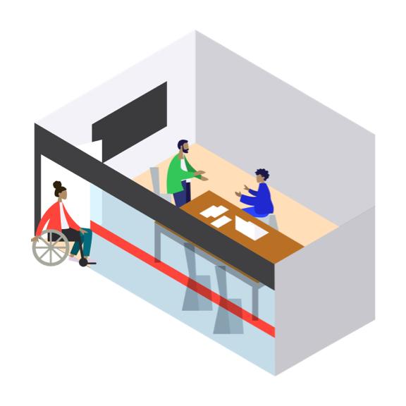
Our design teams work to create spaces in which everyone is considered the intended occupant, fostering conditions for inclusion, equity and belonging. Building blocks are common, repetitive, spatial elements that should have consistent dimensions and be applied throughout the workplace. Baseline blocks must be applied to legacy sites across IBM’s global portfolio. Fundamental blocks must be applied to all new projects, including renovations and new builds. Aspirational blocks are suggested strategies to implement where possible, especially for flagship locations.
- Turning circles
- Clear floor space
- Doorway dimensions and clear space
- Power doors operators (PDO)
- Reach ranges
- Knee clearences
- Pathways
- All-gender restrooms
- Tonal contrast
Turning circles
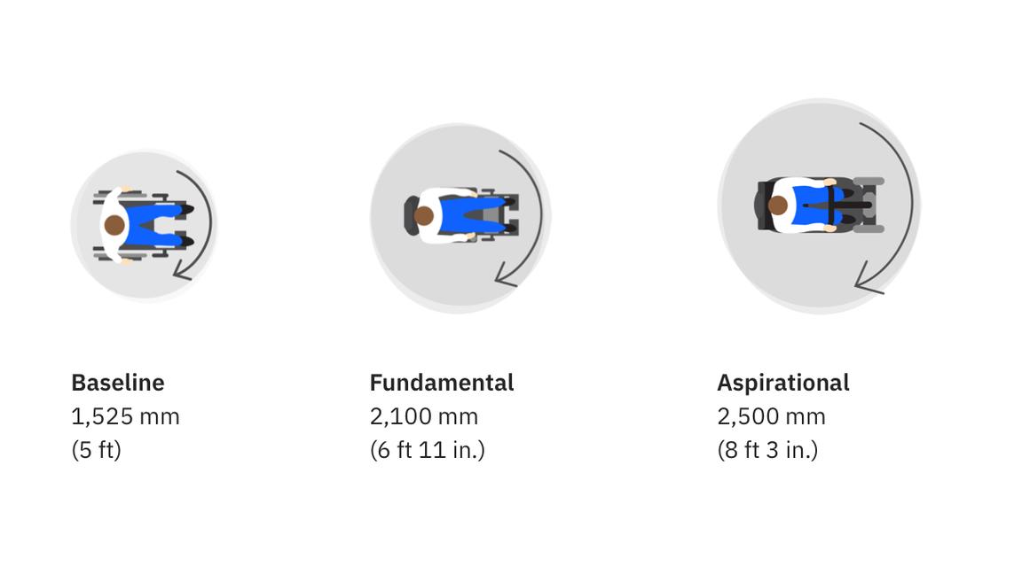
Fundamental turning circles should be provided at key decision points in routes of travel and in all areas with dead-end conditions to provide adequate space for a person to turn around without having to back up. Due to unique conditions, some space types may require larger or smaller maneuvering space—so make sure to verify within the space types requirements. Turning circles should always be clear of any obstruction or overlap with any fixtures, furniture or other parts of the built environment.
Baseline
Code requirements serve very few. Less than 50% of persons using manual and power wheelchairs can make a 360° turn in a 1,525 mm (5 ft) turning circle.
Fundamental
A turning circle that will accommodate 95% of persons using manual and power wheelchairs would be 2,100 mm (6 ft 11 in.) and 50% of scooters.
Aspirational
An additional 685.8 mm (1 ft 3 in.) would accommodate almost everyone. A 2,500 mm (8 ft 3 in.) turning circle would accommodate 95% of scooters used.
Clear floor space
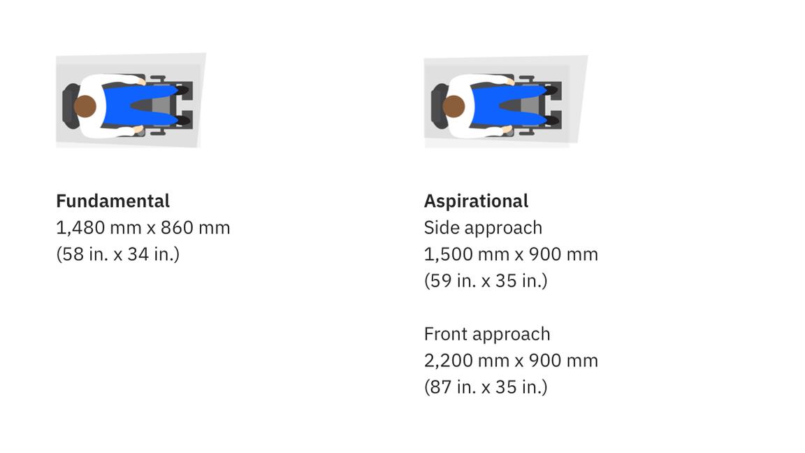
There are many types and sizes of wheeled mobility devices on the market, including manual chairs, powered chairs and electric scooters. The universal clear floor space to accommodate 95% of the population using wheeled mobility devices is at minimum 860 mm x 1,480 mm (34 in. x 58 in.), trending towards 900 mm x 1,500 mm (5 ft x 3 ft) as a best practice.
Clear floor space should be provided in front of all:
- Controls, such as light switches, push buttons for power-operated doors
- Amenities, such as waterpoints and coffee stations
- Appliances, such as refridgerators and microwaves
- Workplace features and tools, such as technical equipment and whiteboards
Clear floor space should also be incorporated into seating arrangements and areas of assembly so that a person using a mobility device can use the clear floor space without having to modify any furniture.
All clear floor spaces should be located on an accessible path of travel and always be clear of any obstruction or overlap with fixtures, furniture or any path of travel.
Doorway dimensions and clear space
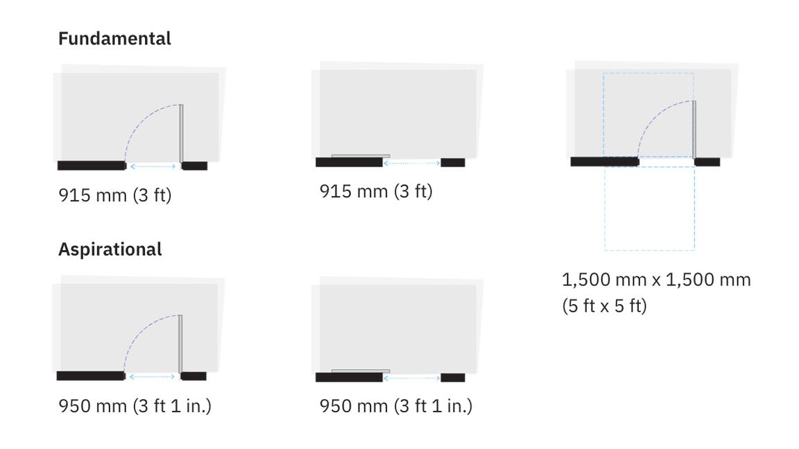
With the swing door open 90°, the door’s clear opening width is measured between the face of the door and the stop on the strike jamb.
With sliding doors, the door’s clear opening width is measured between the edge of the door when fully open and the stop on the strike jamb.
At minimum, all legacy sites should provide doors with a clear door width that’s the AD’s required 815 mm (2 ft 8 in.) measurement.
The fundamental requirements for swing and sliding doors include:
- A clear door width of at least 915 mm (3 ft).
- A maneuvering space measuring 1,500 mm x 1,500 mm (5 ft x 5 ft) on each side of the door. The maneuvering space must be clear of any obstruction.
- Door hardware that does not project more than 100 mm (4 in.) from the door surface, and does not require pinching or twisting to operate.
Where possible, consider implementing the aspirational dimension clear door width of 950 mm (37 in.) as it will accommodate an even greater percentage of the population who use wheeled mobility devices.
Power doors operators (PDO)
Location
Provide PDOs in the following locations:
- All main building entrances
- Doors that have closers, electromagnetic locking devices or no latch side clearances
- Doors entering publicly accessible reception areas
- Doors entering into 25% of enclosed, accessible collaboration spaces
- Accessible facilities, including washrooms, change rooms, copy and print rooms, and support spaces
PDOs and card access
- Where PDOs and card access are provided, locate them immediately adjacent to each other and consistently placed and configure them throughout the building.
- Where co-located, provide automatic activation of PDOs through the use of a security card.
Features and installation
PDOs should have or be:
- The international symbol of accessibility
- A matte, honed, flamed, bushed surface from adjacent surfaces
- Tactile features
- Operable using a closed fist
- Located between 600 mm to 1,500 mm (24 in. to 59 in.) from the door swing, and more than 600 mm (24 in.) from an inside corner
- Installed on a wall or pedestal adjacent to the accessible path of travel
- Provide cane-detectable safety guards where a door will swing into an area where there may be people crossing or, alternately, recess the door so that it doesn’t open into a pathway
Selection
Use an elongated PDO that’s at minimum 150 mm x 725 mm (6 in. x 29 in.), located between 200 mm to 900 mm (8 in. to 35 in.) above the finished floor (AFF).
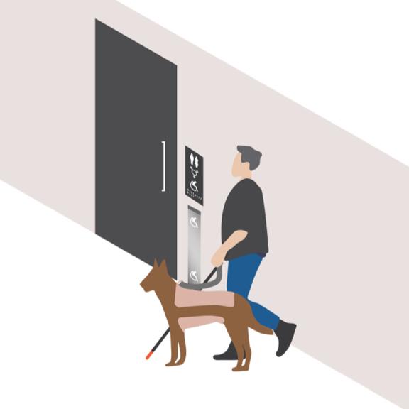
Reach ranges
The height of elements within the workspace is critical to creating a flexible, independently usable environment. Ensure all elements are reachable from the seated position or for a person of shorter stature. These guidelines include providing adequate access to elements within workspaces, amenity spaces and building controls that are to be operated.
To accommodate persons using mobility devices:
- The centerline of elements should be located between 700 mm (28 in.) and 1,050 mm (41 in.) above the finished floor.
- Elements intended to be graspable, such as outlets and data ports located within a table, should be located not more than 500 mm (20 in.) from the face of the obstruction.
- Building service elements can be located at a lower limit of 460 mm (18 in.).
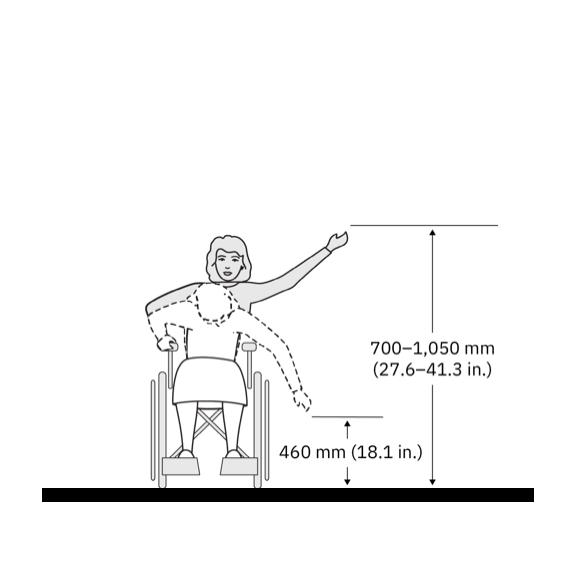
Side-reach range
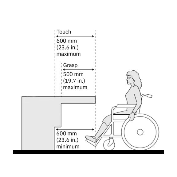
Reach range over an obstruction
Knee clearences
Providing knee clear space at counters, desks and tables is essential for an equitable experience within the workplace, and to ensure the space is functionally accessible. Where services are provided, such as reception counters and cashiers, providing face-to-face interaction through a forward approach is important to an equitable experience.
Knee clearance should at minimum provide:
- Clear width* of 860 mm (34 in.)
- 500 mm (20 in.) deep
- Clear height of 735 mm (29 in.) at the front edge
- Surface height max 860 mm (34 in.)
- Clear height of 350 mm (14 in.), AFF at a point 600 mm (24 in.) back from the front edge
*Consider using the aspirational dimension for turn circles where possible or appropriate.
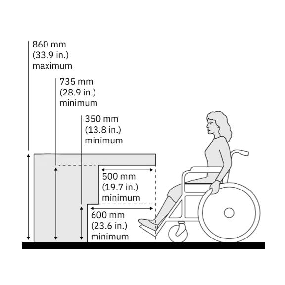
Clear knee space
Pathways
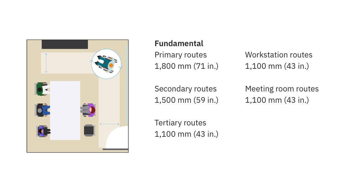
Primary routes must be at least 1,800 mm (71 in.) in width. They are intended for frequent, two-way travel. Primary routes connect with the main entry point and are designed to avoid dead ends.
Secondary routes must be at least 1,500 mm (59 in.) in width. They are intended for frequent, one-way travel. Secondary routes connect with the primary rout within 30 m (98 ft 5.1 in.). Where dead ends exist in secondary routes, provide a 2,100 mm (83 in.) turning circle.*
Tertiary routes must be at least 1,100 mm (43 in.). These routes are intended for limited occupant use one-way travel and should connect with secondary or primary routes within 30 m (98 ft 5.1 in.). Where dead ends exist in tertiary routes, provide a 2,100 mm (83 in.) turning circle.*
Workstation routes must be at least 1,100 mm (43 in.) and include a 550 mm (22 in.) clearance for the chair space so that space is provided for the chair outside the clear path. Where the workstation route serves more than 8 seats, or is longer than 7.5 m (24 ft 7.3 in.), the route must not terminate at a dead end without providing a 2,100 mm (83 in.) turning circle* at the dead end outside the workstation seats.
Meeting room routes in accessible meeting rooms must include an adequate path throughout the room to provide access to all services, including whiteboards and any technology. This path must be at least 1,100 mm (43 in.) wide and include a 550 mm (22 in.) clearance for chair space so that space is provided for a chair outside the clear path. Include a 2,100 mm (83 in.) turning circle* within the meeting room clear of the table and allocate a space outside the accessible route to store a chair
*Consider using the aspirational dimension for turn circles where possible or appropriate.
All-gender restrooms
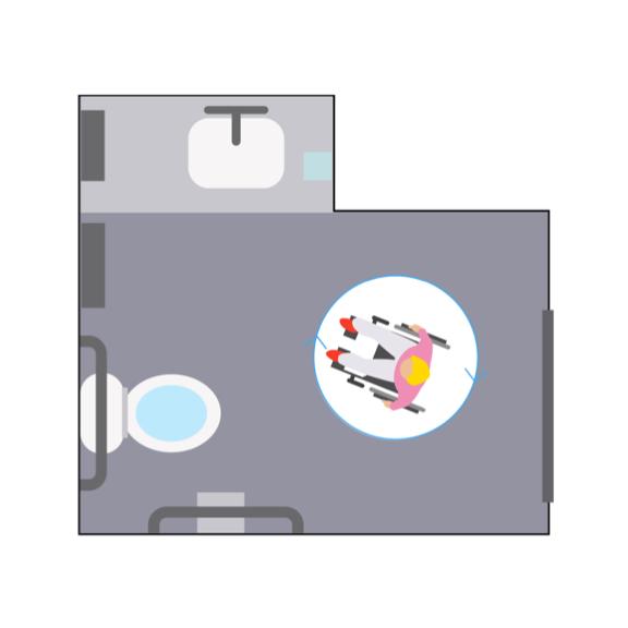
Accessible all-gender restrooms provide a space that’s equitable and designed for everyone. Check local code requirements as all-gender restrooms are mandated in some jurisdictions.
Fundamental
The following ratios apply to newly leased sites:
- The number of all-gender restrooms should be driven by local code, where existing.
- Provide a minimum of one accessible all-gender restroom facility per washroom core per building.
Adjacency
Unless there are site constraints, all-gender restrooms should be centrally located, immediately adjacent to gender-specific restrooms. Where immediate adjacency is not provided, it should be located no further than 45 m (147 ft 7.7 in.) from the gender-specific restrooms.
Aspirational
Where possible, it’s recommended to provide a minimum of one accessible all-gender restroom per each grouping of gendered restrooms.
Tonal contrast
Tonal contrast is a percentage value measuring the difference between two surfaces. The greater the difference in brightness levels, the greater the contrast.
Tonal contrast levels are central to how people navigate and understand the built environment. For effective implementation, tonal contrast should be used thoughtfully and consistently throughout an environment to identify key zones, destinations, features and hazards.
For key elements in the built environment, the contrast level should be at least 50%, whereas the contrast level on signs and pictograms should be at least 70%.
Tonal and brightness contrast is measured through light reflectance values (LRVs) and comparing the adjacent colors’ LRV and the calculation for determining tonal contrast is as follows: Tonal contrast = [(B1-B2) x 100] / B1 (B1: Color 1, B2: Color 2)
Fundamental
Tonal contrast should be provided between:
- Floor surfaces and walls, folding partitions or baseboards
- Doors and door frames from surrounding wall surfaces
- Hazards like providing contrast strips at the top of each set of stairs and vision strips across glass walls and sidelights
- Handrails from surrounding surfaces
- Elevator doors from adjacent wall surfaces, cab sill from lobby floor
- Kitchen counters from the wall or backsplash
- Casework from adjacent wall
- Washroom accessories like grab bars, shelves, and soap and towel dispensers from surrounding surfaces
- Controls and operating mechanisms from mounting surface

