Modeling virtualization with the System 9500
This example shows how to configure a FlashSystem 7300 and have its capacity virtualized by a FlashSystem 9500.
Open an existing project. This example opens an existing project then creates a 9500 storage system (without defining the capacity,
Figure 360). From the project
view, select Add Product> Select a Storage Family > System 9500.
a. Enter a Storage Device Name (example uses “Virtualizing Controller”).
b. Select the Site assignment.
c. Click Submit.
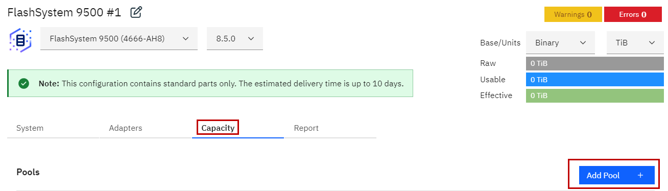
Figure 360 9500 Virtualizing Controller
6. Create a FS7300 Back-end Storage System. Define the capacity (Add Product> Select a Storage Family > System 7300).
a. Select Add Pool. This example creates a data reduction pool with 20% thin
provisioning and 30% compression. Click Submit.
b. Create one array (Add Array), setting the Effective Capacity to 100 TiB of
NVME drives (reverse-calculates number of required drives). Click Submit.
c. Create a second array (Add Array) with 20 NVMe drives (forward-calculates
effective capacity). Click Submit.
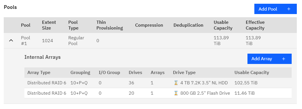
Figure 361 7300 Back-end Storage System
7. Next from the Projects view (click the Project name), select the Capacity, then Virtualize to start creating the virtualization (Figure 362 on page 409).

Figure 362 Virtualize
Figure 363 Select Existing Virtualize Pool
8. You can choose to create a new system
Figure 363 on page 409
or select an existing system to be the Virtualizing Controller, as shown in
Figure 364 on page 410.
(General configuration issues and options are summarized in “Virtualized pools”.)
(General configuration issues and options are summarized in “Virtualized pools”.)

Figure 364 Creating virtualization
9. This example uses an existing FS9500 system. Type a pool name for the Virtualizing Controller, select the system
to be the Virtualizing Controller, then select Next to add the pool to the Virtualizing Controller, as shown in
Figure 365..
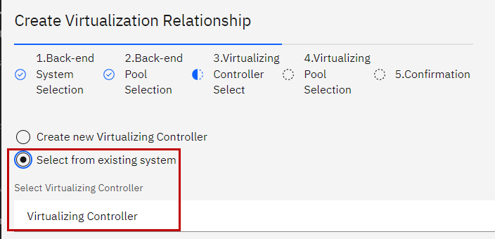
Figure 365 Creating the virtualizing pool
This creates a virtualization relationship with the Virtualizing Controller and the Back-end Storage System, as shown in Figure 366 on page 411
and select Submit in
Figure 367 on page 411
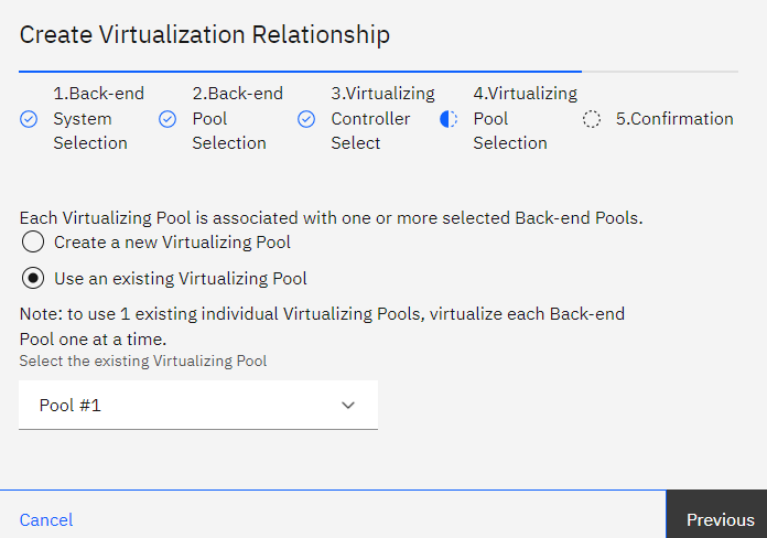
Figure 366 Virtualization relationship

Figure 367 Submit Virtualiztion
The virtualized back-end pool is identified with the cloud icon to the left of the pool name, as shown in
Figure 368 on page 412.
Selecting the cloud icon takes you to the capacity view of
 the
Virtualizing Controller.
the
Virtualizing Controller.
the
Virtualizing Controller.
Figure 368 Virtualized pool in the Back-end Storage System
The capacity numbers from the Back-end Storage System have been applied to the Virtualizing Controller. The Back-end Storage System now has 448.07 TiB of effective capacity and the
Virtualizing Controller has 132.7 TiB of effective capacity. The reason is, parts of data reduction have moved to the Virtualizing Controller because the workload is applied to the pool of
the Virtualizing Controller where the data comes from, as in
Figure 369. Thin provisioning,
compression and deduplication are attributes of the data.

Figure 369 Virtualizing Controller and back-end storage capacity
The Virtualizing Controller does the thin provisioning as follows:
▪It applies the 20% thin provisioning.
▪It reduces the pool in the Back-end Storage System by the 20%.
The pool in the Back-end Storage System still has the 30% compression since originally the back-end pool was defined as a DRP. By default, when you virtualize a pool, the pool in the
Virtualizing Controller becomes a regular pool. You can change the pool type for both the Virtualizing Controller and Back-end Storage System pools but some combinations are not
recommended. In this example, the change that the Virtualizing Controller makes to a DRP pool generates a warning message, as shown in
Figure 370 on page 413.

Figure 370 DRP warning message
Now thin provisioning and compression are applied to the pool in the Virtualizing Controller, not the pool in the Back-end Storage System anymore. See
Figure 371.
Figure 371 Thin provisioning and compression applied to the pool in the Virtualizing Controller
Data reduction now takes place and is controlled from the Virtualizing Controller. The data reduction values can no longer be modified/changed from the back-end pool. The pool of the
Virtualizing Controller can be changed back to a regular pool.
From the Details report, you see that we have mixed drive technologies (NVMe and drives). And there is one Mdisk, since one pool was defined in the Back-end
Storage System, as shown in
Figure 372.

Figure 372 Details report for a Virtualizing Controller
Additional arrays can be added to both the virtualizing and the virtualized pools.