Creating virtualization relationships: “Virtual pools sample”
This section describes how to use the configuration wizard to set up pool virtualization. You access the wizard to add or edit pool virtualization through any of these contexts:
▪The action menu of a system in the Systems list of a project. (For the example in this section, we use this action menu to access the wizard.)
▪The action menu of a pool in the Capacity tab of a specific system.
▪The drop-down menu of the system tile in the Canvas. (This graphical user interface is described in
“Canvas tab (graphically depicts the products in a project)”.)
The following sample project demonstrates the options and concepts of virtualization:
1. Create a sample project using the method that is described in
“Hosts tab (configure the hosts in a project)” on page 48.
For our
Virtual pools sample project, we accept most of the default settings. The result is a typical, simple Storage Modeller project. Where necessary, we
applied settings to components in our sample project, as listed in
Table 5.
Table 5 Virtual pool default settings
|
System type
|
Adapter card
|
# of pools
|
# of drives per array
|
|
FS5200
|
16 GB FC 4-port
|
1
|
12
|
|
FS7200
|
16 GB FC 4-port
|
3
|
24 for NVMe
6 for Tier 1 SSD 6 for Tier 1 SSD
|
Figure 39 on page 37
shows the Systems list view of our
Virtual pools sample project.

Figure 39 Systems list: Virtual pools sample project, with the action menu visible
Create a virtualization relationship on the FS5200 system
2. Create the first part of a virtualization relationship on the FS5200 system.
a. Click the action menu at the right of the row for this system and select Virtualize.
The Create Virtualization Relationship wizard is displayed.
Storage Modeller displays a pop-up message when your Virtualize operation is not recommended. For example, when a pool contains arrays of different tiers, you are advised to not virtualize.
The Create Virtualization Relationship wizard is displayed.
Storage Modeller displays a pop-up message when your Virtualize operation is not recommended. For example, when a pool contains arrays of different tiers, you are advised to not virtualize.
|
▪The Virtualize action that you selected (Figure 40) represents completion of the first step of virtualization, “Back-end System Selection.” As a result, the configuration wizard immediately takes you to Step 2 (not Step 1) of the
virtualization process.
▪We configured the FS5000 system with only one pool. So only that pool is listed for us to select.
▪As explained at the beginning of this procedure, you also can do virtualizations like this in the Canvas user interface. There, you access the same configuration wizard.
|
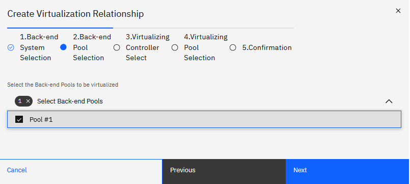
Figure 40 Virtualization wizard, Step 1 of 5: pool selection, with an expanded list view
b. The default selections are valid for our sample virtualization, so click
Next.
The 3. Virtualizing Controller Selection panel of the wizard is displayed(Figure 41).
The 3. Virtualizing Controller Selection panel of the wizard is displayed(Figure 41).
3. Choose the Virtualizing Controller that you want to use. (We need the second option.):
– Select from existing system.
No configuration is required for this option. Click
Next.
– Create new Virtualizing Controller.
This option requires that you specify the following attributes:
• A valid system model in the drop-down menu. SVC is a typical
choice.
• The assigned Site, if you are working with a multi-Site project.
• A unique name for the Virtualizing Controller, if you want to change the default name, which is
SVC #1 initially.
We select
Create new Virtualizing Controller
and immediately click Next, because the default settings meet our needs.

Figure 41 Virtualize the back-end Storage system and create the Virtualizing system
4. Select new or existing Virtualizing Pools for your virtualization.
|
What are the rules for Virtualizing Pools?:
Storage pools inside the hypervisor (the Virtualizing Controller) must be contained in a Virtualizing Pool, which has these traits:
▪Can contain more than one of a storage system’s pools.
▪Can exist with other Virtualizing Pools in a single Virtualizing Controller.
|

Figure 42 Select a Virtualizing Pool to associate with one or more Back-end Pools
The options are as follows:
– Create a new common Virtualizing Pool.
– Use an existing common Virtualizing Pool.
– Create two new individual Virtualizing Pools.
|
Note: For our FS5200 virtualization sample, we create a single Virtualizing Pool now. Later, when we work on the FS7200 virtualization, we decide to use
that same Virtualizing Pool for the pools in both the FS5200 system and the FS7200 system.
|
a. For our Virtual pools sample project, we choose the first option,
Create a new common Virtualizing Pool.
5. Review the summary of actions that the wizard will take when you click
Submit. If you need to make changes, click Previous until you reach the step that you want to modify.

Figure 43 Confirming the
Create Virtualization Relationship
operation
Notice that so far, our virtualization encompasses the FS5200 system only. Soon in this procedure, we will virtualize the pools in the FS7200 system.
6. The actions that are listed in Step 5. Confirmation match our needs, so we
click Submit.
The virtualization relationships for the FS5200 system are applied.
The virtualization relationships for the FS5200 system are applied.
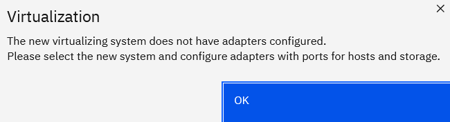
7. Click OK to confirm the following prompt regarding how the new
virtualizing system requires an adapter:
In these steps, we worked through the
Systems list page to create the virtualization relationship from the Systems page. So, we are returned to that page and see the newly created SVC
system in the list of systems.
You can go to the Canvas page to get a graphical perspective on the virtualization relationship, as shown in
Figure 44:

Figure 44 The Canvas view of virtualization for the FS5200 system
8. Continue working in the Systems list, and configure adapters for the new Virtualizing Controller, which is
SVC #1 in our sample project:
a. Click SVC #1 in the Systems list. The SVC #1 system page is displayed with
two error messages:
• SVC #1 lacks an adapter with the Usage “Node to Node”.
• SVC #1 lacks an adapter with at least one port pair of Usage “Host I/O” and at least one port pair
of Usage “Storage.”
b. We click the Adapters tab in this page and click the edit icon in the row
of an “Unused” slot.
The Edit Adapter dialog box is displayed.
The Edit Adapter dialog box is displayed.
c. We select 16Gb FC 4 Port Adapter in the
Type drop-down menu.
d. We click Save, because all defaults are OK, and these defaults include the
port pair characteristics that are mentioned in the error messages.
The error messages go away.
The error messages go away.
Add the FS7200 system to the virtualization relationship
9. Create the second part of our sample virtualization relationship for the FS7200 system.
a. Click the action menu at the right of the row for this system and select Virtualize.
The Create Virtualization Relationship wizard is displayed.
The Create Virtualization Relationship wizard is displayed.
As explained for the FS5200 system, the wizard takes us directly to Step 2, Back-end Pool Selection. By default, the three regular Back-end Pools that we created on the FS7200 system are
selected.
b. We want all the selected pools to be virtualized, so we make no changes and click
Next.
The 3. Virtualizing Controller Selection panel of the wizard is displayed.
The 3. Virtualizing Controller Selection panel of the wizard is displayed.
10. Choose
Select from existing system
so that the three FS7200 pools work with the Virtualizing Controller that we have already created:
SVC #1.
11. Click Next.
The 4. Virtualizing Pool Selection panel of the wizard is displayed.
The 4. Virtualizing Pool Selection panel of the wizard is displayed.
12. Specify which Virtualizing Pool to use for the three FS7200 pools.
a. We want a consolidated virtualization system, so we select
Use an existing common Virtualizing Pool.
A selector list for existing Virtualizing Pools is displayed.
A selector list for existing Virtualizing Pools is displayed.
b. We select VPool #1, the only option that exists in our sample system.
The 5. Confirmation panel of the wizard is displayed.
The 5. Confirmation panel of the wizard is displayed.
13. We review the 5. Confirmation wizard panel. We must confirm the following
actions that the wizard will take to augment the virtualization system that already exists for our FS5200 device:
– System to be reused: SVC #1, type: SVC
– Pool to be reused: VPool #1
– Virtualization Relationships to be created:
•
System 7200 #1 7200 Pool #1 virtualized by SVC #1 VPool #1
•
System 7200 #1 7200 Pool #2 virtualized by SVC #1 VPool #1
•
System 7200 #1 7200 Pool #3 virtualized by SVC #1 VPool #1
14. The actions that are listed in Step 5. Confirmation match our needs, so
we click Submit.
The
Create Virtualization Relationship
process is complete. We used the configuration wizard to virtualize 4 regular pools that existed in two System devices.
Notice that an “adapters” prompt like the one for the FS5200 system did not appear. The resolution of adapter errors that we achieved for SVC #1 applies to the configuration for the
FS7200.