Learn how to replace the disk drive backplane in
the IBM®
Power® System S812LC (8348-21C) system.
Procedure
- Ensure
that you have the electrostatic discharge (ESD) wrist strap attached.
If not, attach it now.
- Remove the replacement disk drive backplane and cables
from the protective plastic envelope.
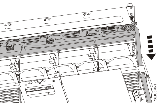
- Carefully pass the fan signal cable, drive power cable, and drive signal cables through the
chassis to install them, as shown in Figure 1.
Figure 1. Installing the drive cables
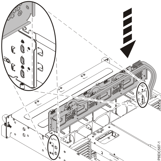
- Using the alignment channel, lower the disk drive backplane straight into the chassis, as shown in Figure 2.
Figure 2. Installing the disk drive backplane
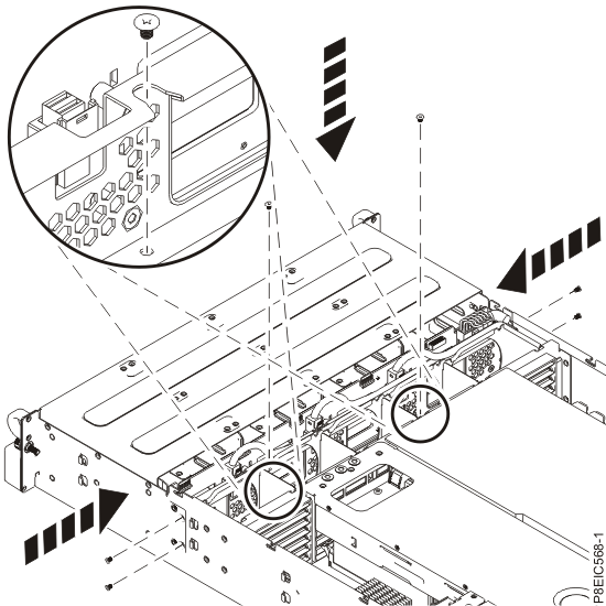
- Replace two screws into the bottom of the disk drive backplane, as shown in Figure 3.
Figure 3. Replacing the disk drive backplane screws
- Replace 2 or 4 screws into the sides of the chassis to secure the disk drive backplane, as shown in Figure 3.
- Fully insert the front drive trays. For instructions, see Replacing a front drive in the 8348-21C.
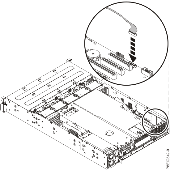
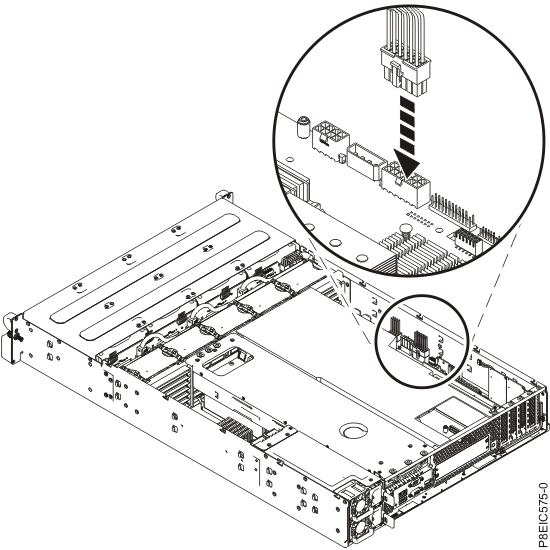
- Replace the front fan signal cable in the system backplane, as shown in Figure 4.
Figure 4. Replacing front fan signal cable
- Replace the front drive
power cable in the system backplane, as shown
in Figure 5. Ensure that the cable latch clip snaps into
place on the connector.
Figure 5. Connecting the front drive power cable
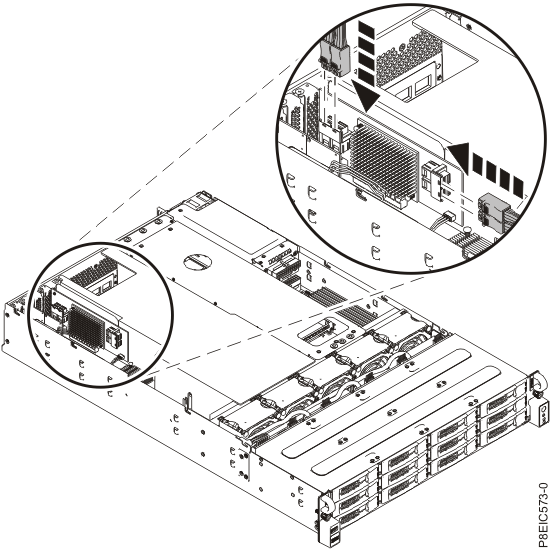
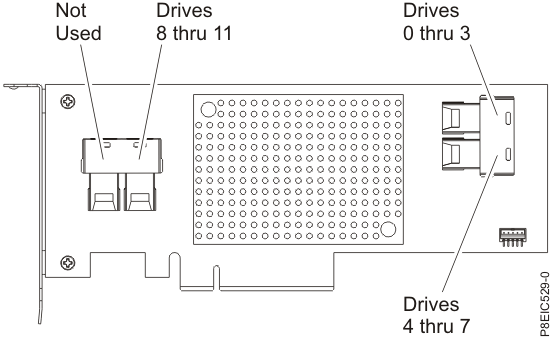
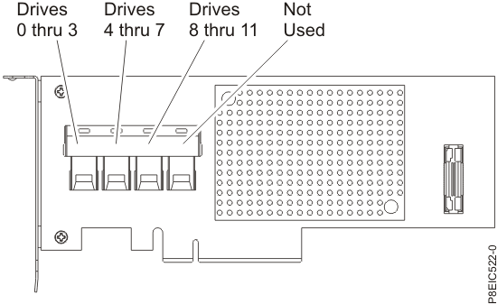
- Using the labels, connect the three drive signal cables to their corresponding connectors on
the drive PCIe adapter, as shown in Figure 6, Figure 7, and Figure 8. Ensure that the cable latch clip snaps into
place on the connector.
Figure 6. Connecting the drive signal cables
Figure 7. Feature EC3S drive cable connector details
Figure 8. Feature EC3Y drive cable connector details
Be sure to route the drive cables such that the cards do not bend and that other components
are forced out of the way.
- Replace the fans. For instructions, see Replacing the fan in the 8348-21C.
