Configuring your IBM Storage Scale solution
When you add an IBM Storage Scale product to your solution, the following four tabs are used to configure or summarize information:
System tab
You can configure your IBM Storage Scale solution by using the auto-calculate function (for a subset of the ESS products) or by manually configuring the products.
Auto Calculate
When you add one of the following products to your solution, the Auto Calculate function is the default for configuring your solution:
▪ESS 3500
▪ESS 3200
▪ESS 3000
▪ESS 5000 SCx
▪ESS 5000 SLx
▪Scale System 6000
To configure your product with automatically calculated information, follow these steps:
1. After you add one of the above products, the Auto Calculate window opens
by default.
|
Note: The Auto Calculate function does not apply to the following products:
▪ESS Management Server
▪ESS Protocol Node
▪Scale System Utility Server
|
2. Fill in the fields on the Auto Calculate window and click Auto Calculate to create a
table (red box at bottom of Figure 238)
that contains several options of product configurations.
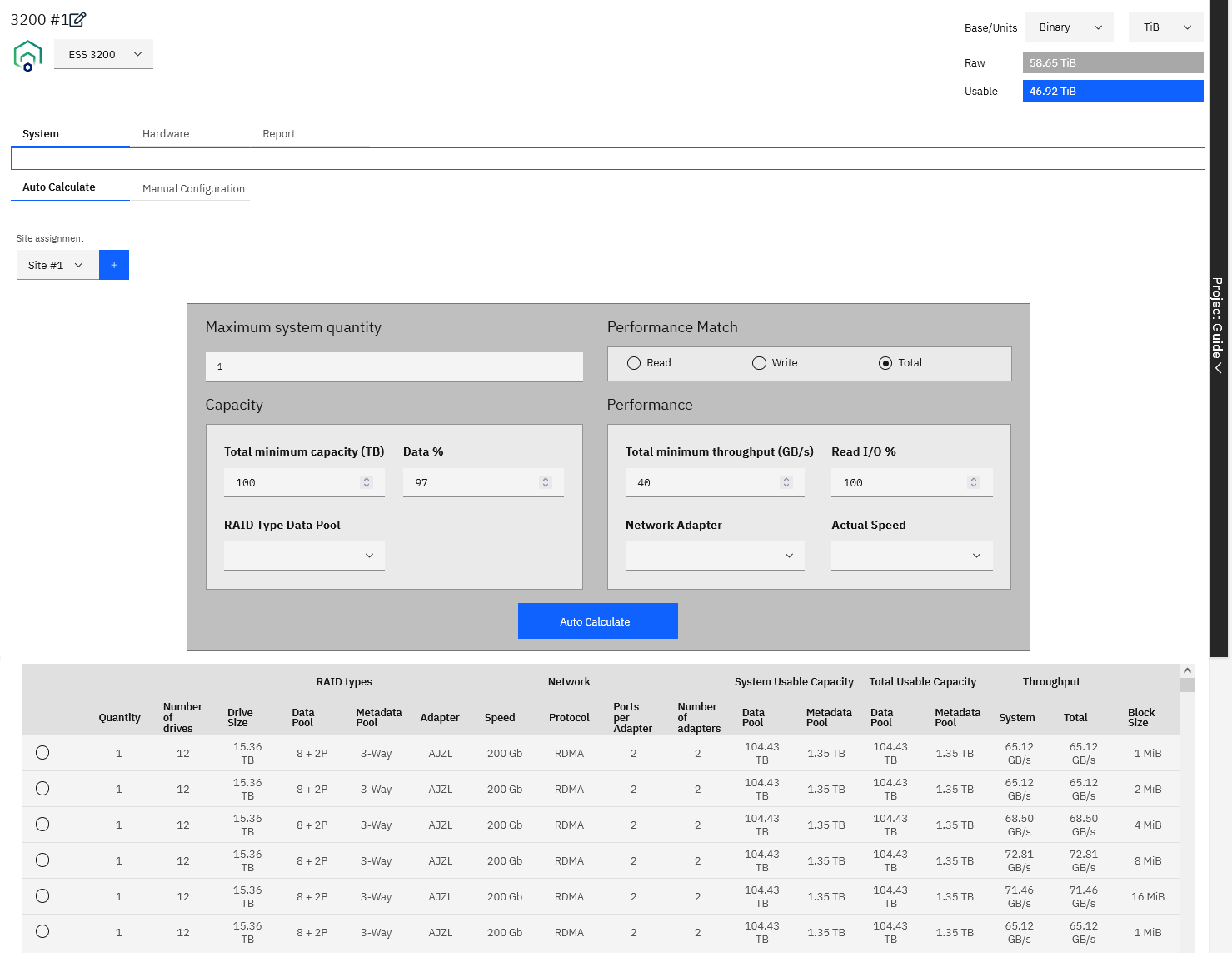
Figure 238 Auto Calculate tab - ESS 3200
3. Select the radio button for one of the configuration options in the table. The configuration window is displayed
and populated with the selected configuration information.
Manual configuration
To configure your product with automatically calculated information, follow these steps:
1. Click System>Manual configuration.
2. Fill in the information.

Figure 239 Manual Configuration tab - ESS 3200
The Manual configuration tab consists of four main sections:
▪Capacity
▪Network
▪Adapters
▪Performance
Capacity
▪For all models except for the ESS 3500, the Capacity is configured as follows:
The values in the Capacity section together with the Usable Capacity table on the right side of the window are used to determine the
System and Total values of the:
– Data Pool Usable Capacity
– Metadata Pool Usable Capacity
Figure 240 on page 291
shows how the values in the Capacity and the Usable Capacity table are used to calculate the Data Pool and Metadata Pool Usable
Capacity.

Figure 240 Manual Configuration tab - Usable Capacity calculation for ESS 3200
▪For the ESS 3500, configure the Capacity as follows:
a. Click Configure Capacity.

Figure 241 Manual Configuration tab - ESS 3500
The Configure Capacity window is displayed.
b. Choose the ESS 3500 Solution type and fill in the corresponding information.

Figure 242 Configure Capacity - ESS 3500
The ESS 3500 Solution types are as follows:
• ESS 3500 Performance Model
If you choose the Performance Model, only the
NVMe Enclosures section is enabled. The HDD Enclosures section is disabled.
• ESS 3500 C1 (Capacity Model - 1 Enclosure)
• ESS 3500 C2 (Capacity Model - 2 Enclosures)
• ESS 3500 C3 (Capacity Model - 3 Enclosures)
• ESS 3500 C4 (Capacity Model - 4 Enclosures)
• ESS 3500 C5 (Capacity Model - 5 Enclosures)
• ESS 3500 C6 (Capacity Model - 6 Enclosures)
• ESS 3500 C7 (Capacity Model - 7 Enclosures)
• ESS 3500 C8 (Capacity Model - 8 Enclosures)
If you choose any of the Capacity Models, fill in only the
HDD Enclosures section is enabled. The NVMe Enclosures section is disabled.
• ESS 3500 H1 (Hybrid Model - 1 Enclosure)
• ESS 3500 H2 (Hybrid Model - 2 Enclosures)
• ESS 3500 H3 (Hybrid Model - 3 Enclosures)
• ESS 3500 H4 (Hybrid Model - 4 Enclosures)
• ESS 3500 H5 (Hybrid Model - 5 Enclosures)
• ESS 3500 H6 (Hybrid Model - 6 Enclosures)
• ESS 3500 H7 (Hybrid Model - 7 Enclosures)
• ESS 3500 H8 (Hybrid Model - 8 Enclosures)
If you choose any of the Hybrid Models, both the
NVMe Enclosures section and the HDD Enclosures section are enabled.
c. Click Configure. The Manual Configure tab is displayed with the summary table filled
in.

Figure 243 Manual Configuration tab - Summary table for ESS 3500 H1
The Summary table shows one line each for the NVMe Enclosure and the HDD Enclosure. It also shows the total for both types of enclosures.
|
Note: Depending on the type of ESS 3500 Solution that is chosen, the table varies:
▪For Performance Model: Only the NVMe line is in the table.
▪For Capacity Model: Only the HDD line is in the table.
▪For Hybrid Models: Both the NVMe and HDD lines are in the table. See
Figure 243.
|
If you change the ESS 3500 Solution, for example from 1 enclosure to 3 enclosures, only the values in the table are unpdated. Extra lines are not added to the table.
▪Network, Adapters, and
Performance
The options you choose in the
Network, Adapters, and Performance sections determine the values in the Workload Output table and the
Read/Write Output table.

Figure 244 Manual Configuration tab - SAS adapters per server details
The total number of adapters, including the SAS adapter, is still 8. In the Manual Configuration tab the user selects the adapters
per server, and there are two servers. Therefore, when the user selects 4 in Manual Configuration, it is the same as adding
8 in the Hardware tab.
The maximum number of
SAS adapters per server depends on the ESS 3500 model that is selected:
– ESS 3500 Performance Model: The maximum value is 0.
– Capacity Models - ESS 3500 C1 and C2 / Hybrid Models - ESS 3500 H1 and H2:
The minimum value is 2 and the maximum value is 4. Since adapters are added in pairs, the options (in the
SAS adapters per data server field) are actually 1 or 2. This means that if the user adds 1 SAS adapter, then they can add only 3 network adapters (Quantity per data server
field). If they select 2 in the
SAS adapters per data server field, then they can add only 2 network adapters.
– Capacity Models - ESS 3500 C3 and C4 / Hybrid Models - ESS 3500 H3 and H4:
The only value in the
SAS adapters per data server field is 2. Therefore, the user can add up to 2 more network adapters (in the
Quantity per data server field).
Hardware tab
In the Hardware tab, you can perform the following tasks:
▪Configure the adapters to be used in your solution.
▪Change the IBM Storage Scale Edition Package.
▪Change the Subscription/Support Term.
▪ESS 3500 only: Choose the memory option (shown in the red box in
Figure 245). The default is
64 GB DDR4 32 MT/s Memory DIMM. You can also choose 128 GB DDR4 Memory DIMM.

Figure 245 Hardware tab - Memory option for ESS 3500
To add, edit, or delete an adapter, click the arrow to expand the system row and click Add Adapter in the
Adapter tab.
The option you select in the
IBM Storage Scale Edition Packages field changes the Description that is displayed in Software tab.
Report tab
The Report tab includes selectable spreadsheets that summarize details of the system’s configuration and the list of parts.
The following spreadsheets are displayed in the Reports tab.
▪Summary: The summary spreadsheet contains ESS configuration details.

Figure 246 ESS - Summary report

Figure 247 IBM Storage Scale Utility Server- Summary report
▪Parts List: The Parts List spreadsheet shows a detailed list of the quantity, machine type models (MTMs), Feature, and a description of the parts that are
configured in Storage Modeller. This list shows what will be included in the CFR file that is then imported into e-config. If the CFR gets rejected, refer to
“What to do if your pre-sales CFR file is rejected” on page 296
for help.

Figure 248 ESS - Parts List report

Figure 249 IBM Storage Scale Utility Server - Parts List report
What to do if your pre-sales CFR file is rejected
During the Pre-sale review, neither the IMPACT package, nor the configuration in StorM can be edited. They are marked as Read Only.
If the review revealed significant problems with the configuration, it will be sent back to the requester with the status
Failed - Needs more work. In that case, both the IMPACT package and the product's configuration in StorM are editable again. All CFR files previously
uploaded to Question 1 are removed from it, but will stay in the Attachments section as a rejected configuration for documentation purposes.
Please correct the configuration based on the reviewer's feedback and upload a new set of completed CFR files to Question 1 of the Pre-sale checklist, before you submit the review request.
For certain products, the StorM-generated CFR files have to be imported into e-config first. All validation warnings have to be addressed to make the configuration complete..
Integrated TDA tab
The Integrated TDA tab contains the ESS Solution Requirements checklist, which consists of questions that define key solution requirements that are needed for your solution design. These
questions help determine technical risk for the solution requirements and is one method of determining that a Storage Technical Review Board assessment is required for your ESS solution.

Figure 250 Integrated TDA tab
The Solution design parameters define the high-level customer requirements for the solution and are measured against the full Solution Group as designed. The questions should be filled out
before you complete your IBM Storage Scale ESS solution design and must be filled out before you finalize your solution. The checklist questions apply to the complete solution or Solution
Group and not the individual products within the Solution Group. The questions are accessible in the Integrated TDA tab as soon as you create the ESS Solution Group.
If your customer-solution requirements fall in a high-risk range, the opportunity is flagged for an STRB assessment. High-risk evaluation is based on both your answers to questions in the
Solution Requirements checklist and on Solution design parameters as designed in Storage Modeller. The STRB assessment engages an IBM Storage Scale expert to guide solution configuration
for high-risk solutions.
STRB Process
When your Solution is flagged for an STRB review, a corresponding notification is displayed in the Products table for your Solution Group and in the Project Guide. When you are ready for
the STRB Storage Scale expert to review your solution, follow these steps:
1. Click the Request STRB Assessment option
in the Actions menu of the Solution Group in the Product Table. The
Request required
STRB assessment item in the Project Guide is checked at the same time.

Figure 251 Solution Group - Action menu
1. A dialog box is displayed that contains an email to be sent to an STRB team member. You can add remarks to the
email before you send it.

Figure 252 Sample STRB email
The STRB team member will contact you to set up and conduct the review to assist with your opportunity design.
2. After the STRB review is successfully completed, click Mark STRB Completed in the
Actions menu. The brown STRB Required indicator in the Products table is changed to a green STRB Completed indicator.

Figure 253 Solution Group - Action menu
The STRB completed item in the Project Guide is automatically checked at the same time.
|
Note: Click Mark STRB Completed after all updates to the configuration are complete in accordance with the STRB review. The
configuration should not be changed after you click Mark STRB Completed.
Changes to the configuration of a product or the content of the Solution Group will revert the
STRB Completed status. If changes are made, evaluate if further review by the STRB team is necessary based on the specific changes and click
Mark STRB Completed again.
|
3. Click Finalize Solution Group in the Actions menu.
|
Note:
You can request an STRB review if you believe your opportunity has high risk and you need assistance from the STRB team, even if the standard risk assessment does not flag an
STRB Required. Click the Request STRB Assessment option in the Actions menu of the Solution Group in the Product Table when you
are ready to have your solution reviewed by an STRB team member. You can finalize your Solution Group at any time, since the STRB is optional.
|
Project Guide - STRB Required vs. STRB Optional
Figure 254
shows the Products table view and Project Guide for a solution where the STRB is required. The
Request required
STRB assessment item is listed in the Project Guide.

Figure 254 ESS Project with STRB required
When an STRB is required, an
STRB Required indicator is included in the Product table view.

Figure 255 STRB Required indicator in product table
Figure 256
shows the Products table view and Project Guide for a solution where the STRB is not required. The
Request optional
STRB assessment item is listed in the Project Guide.

Figure 256 ESS Project with STRB optional
ESS Solution Requirements checklist
Figure 257
shows an example of the questions in the
Requirements tab of the ESS Solution Requirements checklist:
▪What is the overall usable storage capacity required (data and metadata)?
▪What are the overall bandwidth requirements for reading and writing in GBs?
In the ESS Solution Designed section of the ESS Solutions Requirements checklist, STRB Completed is set to yes
when the STRB completed To-Do item in the pre-defined list in the Project Guide is checked. See
“IBM Storage Scale Project Guide” on page 307.
The ESS Solution Requirements checklist questions are updated regularly by the checklist owners, which are the World Wide Technical Leads (WWTLs).

Figure 257 ESS Solution Requirements checklist