 NetView for z/OS, Version 5.4
It is important to understand how your decision to monitor network, local, or LU topology can affect what you see in the views. Each topology displays different information.
As an example, with Advanced Peer-to-Peer Networking®, it makes a difference whether you collect local topology on ENs or on NNs, both in terms of the objects that are present in the views and in how you interpret status. In addition, because the ACTIVATE, INACTIVATE, and RECYCLE commands are issued against various real resources, you must have already obtained the appropriate topology to use these commands from the NetView® management console menus.
Your choices also affect performance. Monitoring local topology or LU topology increases the volume of data sent to the topology manager and RODM because of the additional objects involved. Your choice can also cause frequent view changes.
This section describes the differences between monitoring network, local, and LU topologies so that you know when to use these options. Examples of some options are demonstrated and described in SNA Topology Manager User Scenarios in the sample Advanced Peer-to-Peer Networking network views.
Each NN maintains a copy of the network topology of its subnetwork. This topology database is duplicated in every NN in the subnetwork. The topology manager obtains this data from the nodes and displays the following information:
Because the topology data is duplicated in every network node, you only need to request network topology from a single network node to obtain the network topology of the subnetwork. Network topology, therefore, can include nodes that do not have the topology agent installed. You can obtain network topology only from NNs that have an agent installed. Network topology is not available from ENs.
Network topology displays the nodes and connections used for network routing in the Advanced Peer-to-Peer Networking subnetwork. If you want to monitor just those nodes and connections that are important for Advanced Peer-to-Peer Networking network routing, use network topology without local topology. Local topology displays additional nodes and connections that are not part of Advanced Peer-to-Peer Networking network routing.
Without local topology, you cannot view, navigate to, or issue NetView management console menu commands against underlying ports and links in the network. The view navigation ends at NNs and their interconnecting TGs. You cannot view or navigate to ENs and LEN nodes in the NN domains. This also means that the status of TGs to ENs is not part of the aggregation calculation. Although underlying resources might actually exist in the Advanced Peer-to-Peer Networking network, the data for these resources is not in RODM until you collect it by monitoring local topology.
Lack of local topology data also has implications for TGs and TG circuits that use demand-activated links:
The local topology of a node is specific to that node. Monitoring local topology of NNs adds information about their TGs, links, ports, and adjacent ENs and LEN nodes that is unavailable from network topology.
With this type of monitoring, you can display views of the following resources:
This type of topology monitoring displays status and configuration information for the entire network node domain. This information is useful for understanding and navigating to the underlying links and ports and also connections to the adjacent ENs and LEN nodes. Monitoring local topology of a network node is useful for determining which resources lose Advanced Peer-to-Peer Networking services if the network node has a problem or loses access to the network. The aggregation calculations are more comprehensive when you are monitoring the local topology because it includes the connections to served ENs.
Including local topology of network nodes might be the best way for you to monitor most resources in your network without the added performance hits of monitoring EN local topology. The added performance costs occur because monitoring of EN local topology adds many more resources and topology flows to the RODM processing.
Monitoring local topology data on NNs but not on ENs has implications for TGs and TG circuits with demand-activated links. The status of the TGs or TG circuits from NNs to ENs or from NNs to NNs is displayed as intermediate when the underlying demand-activated link is inactive. Because the local topology is monitored, the topology manager has the link status data. (TG circuit status is calculated according to the rules in Table 21).
When the underlying demand-activated links are activated, TGs and TG circuits are displayed with satisfactory status.
If you have never monitored EN local topology, those objects are not in RODM and cannot be displayed in views. Note that you do not need to be actively monitoring local topology for the objects to be in RODM, just that you have previously obtained local topology (and the resources have not been purged).
Without local topology of ENs and BrNNs:
Monitoring Advanced Peer-to-Peer Networking network and local topology on NNs and Advanced Peer-to-Peer Networking local topology on ENs and branch network nodes displays information about every resource in the network that has an agent. Monitoring local topology of ENs and BrNNs adds information about their TGs, links, ports, adjacent ENs, and adjacent LEN nodes to the views. TGs and TG circuits between all types of nodes (NN to NN, NN to EN, NN to BrNN, NN to virtual routing node, EN to EN, EN to virtual routing node, NN to LEN node, and EN to LEN node) are displayed in the views. When demand-activated links are inactive, TGs and TG circuits show intermediate status. Once the underlying links are activated, the TGs and TG circuits that use these links show satisfactory status.
This way of monitoring provides more comprehensive views; however, it can mean performance trade-offs if you have a large number of nodes and connections in the network. In addition, the complexity of the views displayed increases because of the number of objects in the views.
For subarea networks, network topology includes the CDRMs that are part of active CDRM definitionGroups at the VTAM® (t5Node, interchangeNode, or migrationDataHost) to which the network topology request was sent using the command:
TOPOSNA MONITOR NETWORK NODE=netid.cp
For a subarea local topology monitor request, all resources that are known at the VTAM (t5Node, interchangeNode, or migrationDataHost) to which the request was sent are reported using the command:
TOPOSNA MONITOR LOCAL NODE=netid.cp
These resources include the following resources:
The exceptions are the following resources:
Use a TOPOSNA MONITOR LUCOL NODE=netid.cp command to monitor the logicalUnit, luGroup, and crossDomainResource objects that reside at the VTAM node. Use the LCLNAME parameter to monitor the LU and CDRSC objects that reside at a logicalLink.
For VTAMs that are functioning as both a subarea node and an Advanced Peer-to-Peer Networking node, the network and local topology contains a combination of Advanced Peer-to-Peer Networking and subarea resources.
When you want to specifically monitor network topology from VTAMs that are functioning as subarea nodes, start the collection of network topology for a known, single t5Node, interchangeNode, or migrationDataHost. The VTAM responds with all crossDomainResourceManagers that are known to it. If the VTAM is an interchangeNode, the Advanced Peer-to-Peer Networking network topology is also sent.
You can then bring up the view of crossDomainResourceManagers and select one of the crossDomainResourceManagers. Run the previously built command profile containing the TOPOSNA MONITOR, (NETWORK, LOCAL or LUCOL) commands. See Adding Topology Manager Commands to the Menus for information about building a command profile.
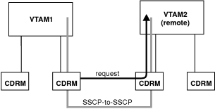
The SNA topology manager resolves the OBJECTID of the remote VTAM and sends the requests to the remote VTAM. See Figure 26 for a pictorial example.
If the network ID is not known (unknown to the t5Node that reported the crossDomainResourceManager), an error message is displayed that states that the TOPOSNA command has failed.
Assume you are a help desk operator and have already started monitoring local topology on the two VTAM nodes (SSCP1 and SSCP2) in NETA. A user calls and reports the inability to log on to an application, and the user knows the LU name. To determine the status of the LU, perform a Locate Resource command with the Extended Search option selected.
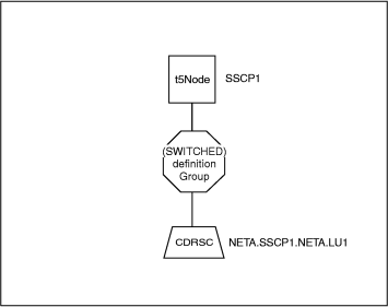
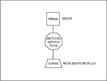
If you perform the locate LU function and specify an LU resource name that is not fully qualified, such as NETA.LU1, two Configuration Parents views might be displayed on your screen, as shown in Figure 27 and Figure 28. Whether you get one or two views depends on your environment (Advanced Peer-to-Peer Networking, subarea, or mixed). See Locating LUs in the Network for additional information about environment considerations when locating a logicalUnit object.
If you know the fully qualified name to be NETA.SSCP2.NETA.LU1 (our example value) and specify it when you perform the locate LU, the SNA topology manager displays a Configuration Parents view such as that shown in Figure 28.
To monitor the LU collection, which in this example is a collection of one, perform one of the following tasks:
TOPOSNA MONITOR,LUCOL,NODE=NETA.SSCP2,LCLNAME=PU1
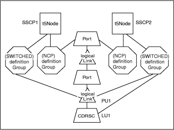
When the LUCOL is run for the logicalLink named PU1 at agent SSCP2, Figure 28 evolves to Figure 29.
Independent LUs are put in context of the logicalLink only by a TOPOSNA MONITOR,LUCOL command, where the LCLNAME parameter equals the logicalLink_name of the used logicalLink. If NETA.LU1 was a dependent LU residing at PU1, the LU is immediately placed in context of the logicalLink and Figure 29 is displayed instead of Figure 28.
Note these several points relative to LU topology:
When a logicalLink is owned by more than one VTAM, monitoring the collection of logicalUnits residing at the logicalLink can be accomplished by selecting the logicalLink on a view and running the More Detail command.
The SNA topology manager performs the following steps to select the VTAM topology agent for the monitoring of the collection of logicalUnits:
TOPOSNA MONITOR,LUCOL,NODE=netid.cp,LCLNAME=localnameWhere localname is the local name of the logicalLink, and netid.cp is the network qualified name of the control point of the agent node.
[ Top of Page | Previous Page | Next Page | Contents ]