Networking on z/OS
Networking on z/OS
Networking on z/OS
|
Previous topic |
Next topic |
Contents |
Glossary |
Contact z/OS |
PDF
How SDLC devices are connected using DLSw Networking on z/OS |
|
|
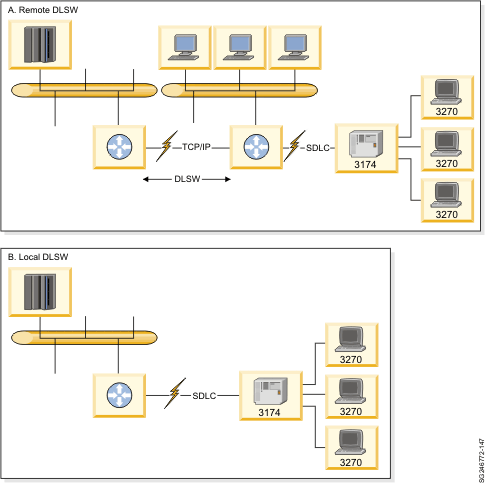
DLSw routers were installed in remote branches. The DLSw router enabled the connection of TCP/IP and SNA LAN-attached workstations to the mainframe. Many remote branches still have SDLC devices like IBM 3174 controllers, banking, or retail controllers. Using the DLSw branch router eliminates the need to connect the SDLC device using a dedicated communication link. Figure 1 shows how an SDLC controller in a remote branch is connected using DLSw routers. Figure 1 depicts the two types of DLSw: remote (A) and local (B).
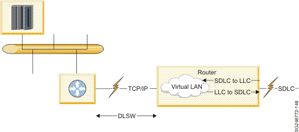
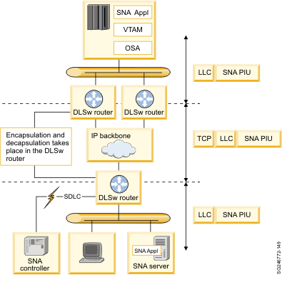
The Remote DLSw configuration in Figure 1 enables the workstations connected to the remote LAN workstations to communicate with either TCP mainframe-based applications using the communication link that connects the two routers, or mainframe SNA application using encapsulated LLC2 in TCP packets (DLSw). The SDLC traffic is converted by the router to LLC2 and is transported using DLSw. Every router has an IP address assigned to its LAN interface. Figure 2 illustrates the representation of the SDLC link inside a DLSw router. In Figure 2, the SDLC link is represented inside the router as a connection to a virtual LAN. Virtual LAN is a LAN implemented inside the router and is not related to a physical LAN interface. The SDLC link is assigned a virtual MAC address, and this MAC address is carried in the encapsulated LLC2 frames. Figure 3 shows the placement of DLSw routers in an IP backbone network. DLSw routers are located at the edge of the network adjacent to the SNA device, mainframe, and server in our example. The DLSw routers perform the encapsulation and decapsulation of the LLC2 frame that carries the SNA path information unit or LLC2 commands and responses. The following points summarize some of the DLSw attributes:
DLSw was the first SNA over IP solution that became available. It is a mature product and you will find that many organizations have implemented this solution. |
 Copyright IBM Corporation 1990, 2010 Copyright IBM Corporation 1990, 2010 |