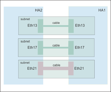
Example network set up for HA configuration
The example shows the network configuration for an high availability implementation.
The configuration is illustrated in the following diagram. The two HA appliances are located in adjacent racks, and are directly connected to each other with the supplied cables. It is recommended that the IP addresses are in separate subnets for each connection (as shown in the diagram). Otherwise you need to take other steps to ensure that data leaves the appliance on the correct Ethernet interface (for example, by setting up routes on the appliance).

The following tables show how the Ethernet ports are configured on the two HA appliances, HA1 and HA2.
| Ethernet port | Example IP address | Port | Description |
|---|---|---|---|
| eth13 | 192.0.10.11 | 5404, 5405 for heartbeat, 2222 for configuration | HA primary group interface |
| eth17 | 192.0.20.11 | 5404, 5405 for heartbeat, 2222 for configuration | HA group alternative interface |
| eth21 | 192.0.30.11 | Each HA queue manager uses a port, starting at 7789 for the first created, 7790 for the second created, and so on, up to 8021 | HA replication interface |
| eth22 | 203.0.113.0 | Data interface |
| Ethernet port | Example IP address | Port | Description |
|---|---|---|---|
| eth13 | 192.0.10.12 | 5404, 5405 for heartbeat, 2222 for configuration | HA primary group interface |
| eth17 | 192.0.20.12 | 5404, 5405 for heartbeat, 2222 for configuration | HA group alternative interface |
| eth21 | 192.0.30.12 | Each HA queue manager uses a port, starting at 7789 for the first created, 7790 for the second created, and so on, up to 8021 | HA replication interface |
| eth22 | 203.0.113.2 | Data interface |