 NetView for z/OS, Version 5.4
All objects are grouped into views according to the view links and graph objects defined in the SNA topology data model. These views are the basis from which you navigate through the network to the underlying real resources.
This section describes the exception views, Advanced Peer-to-Peer Networking® views, and dynamic subarea views available on the NetView® management console.
Exception views are the primary starting point for all view navigation to a failing network resource.
An exception view can be a collection of real, shadow, and aggregate objects that have been defined as exceptions. No connectivity relationship exists between objects in an exception view; it is simply a graphical list of objects. This list can be filtered by the DisplayStatus or UserStatus values of the object. Figure 19 is an example of an exception view.
There can be one or more exception views. The following list contains a few examples of what an exception view can contain:
For more detailed information about defining and filtering exception views, see the IBM Tivoli NetView for z/OS Resource Object Data Manager and GMFHS Programmer’s Guide. Also see, Using Customization Tables and Methods for a description of the FLBEXV exception view table.
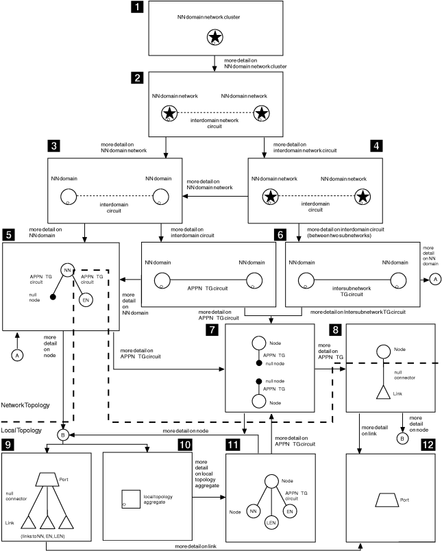
Table 22 describes the Advanced Peer-to-Peer Networking views available on the NetView management console. Figure 20 shows the views in pictorial form to help understand the Advanced Peer-to-Peer Networking view navigation. Reference keys show the correlation between the table and the pictorial diagram.
All Advanced Peer-to-Peer Networking views are created dynamically, except for the first view, SuperclusterView ( 1 ), which is the starting point. Additional information about views is also available:
|
Type of View and Contents of View |
Ref Key |
Used for: | Reached by: |
|---|---|---|---|
| SuperclusterView
The *nnDomainNetworkCluster object, which is an aggregate of the entire Advanced Peer-to-Peer Networking network |
1 | Accessing the objects of the Advanced Peer-to-Peer Networking network | NetView management console tree view |
| *nnDomainNetworkCluster
*nnDomainNetwork objects and *interdomainNetworkCircuit objects |
2 | Showing aggregated status of Advanced Peer-to-Peer Networking resources within the entire network, and view navigation to the next lower-level views (*nnDomainNetwork and *interdomainNetworkCircuit) | Choosing More Detail on the *nnDomainNetworkCluster object |
| *nnDomainNetwork
*nnDomain objects and *interdomainCircuit objects |
3 | Showing aggregated status of Advanced Peer-to-Peer Networking resources within a subnetwork, and view navigation to the next lower-level views (*nnDomain and *interdomainCircuit) | Choosing More Detail on an *nnDomainNetwork object |
| *interdomainNetworkCircuit
*interdomainCircuit objects between *nnDomains in different *nnDomainNetworks |
4 | Showing aggregated status of *interdomainCircuits between two subnetworks, and view navigation to the next lower-level view (*interdomainCircuit) | Choosing More Detail on an *interdomainNetworkCircuit object |
| *nnDomain for Network Node
The appnNN or interchangeNode object of the *nnDomain, the served appnEN or migrationDataHost objects of the *nnDomain, the appnTransmissionGroupCircuit objects that support CP-CP sessions between the network node and its adjacent nodes, and the appnTransmissionGroupCircuit objects between the network node and the virtual routing nodes defined at the network node. View can also contain an *appnTransGroupCircuitCN object. |
5 | Showing status of Advanced Peer-to-Peer Networking resources within an *nnDomain (the network node, its served end nodes, and the appnTransmissionGroupCircuits between the network node and its served end nodes) and view navigation to the next lower-level views (SNA Local Topology, Port-Link, and Advanced Peer-to-Peer Networking TG circuit views) | Choosing More Detail on an *nnDomain object |
| *nnDomain for branch Node
The branch node object of the *nnDomain and the appnTransmissionGroupCircuit objects between the branch network node and the adjacent network nodes. |
None | Showing status of Advanced Peer-to-Peer Networking resources within a branch network node (the branch network node and its appnTransmissionGroups to NNs | Choosing More Detail on an *nnDomain object |
| *nnDomain for Virtual Routing Node
The virtualRoutingNode object of the *nnDomain, and the appnTransmissionGroupCircuit objects between the virtual routing node and the Advanced Peer-to-Peer Networking network nodes within the connection network identified by the virtual routing node |
None | Showing status of Advanced Peer-to-Peer Networking resources within an NN domain for virtual routing node (that is, the virtualRoutingNode and its appnTransmissionGroupCircuits to NNs) | Choosing More Detail on an *nnDomain object |
| *interdomainCircuit
appnTransmissionGroupCircuit objects between two *nnDomains (the *nnDomains might be in same subnetwork or different subnetworks) View can also contain *appnTransGroupCircuitCN object. |
6 | Showing derived status of appnTransmissionGroupCircuits between *nnDomains, and view navigation to the next lower-level view (appnTransmissionGroupCircuit) The status of the appnTransmissionGroupCircuit is derived from its constituent appnTransmissionGroup status values, as shown in Table 21. | Choosing More Detail on *interdomainCircuit object |
| SNA Local Topology
One *nnLocalTopology or *enLocalTopology object for the selected appnNN, interchangeNode, appnEN, or migrationDataHost object |
7 | View navigation to the next lower-level view (*nnLocalTopology or *enLocalTopology) | Choosing More Detail on an appnNN, interchangeNode, appnEN, or migrationDataHost object |
| *enLocalTopology or *nnLocalTopology
The selected appnNN, interchangeNode, appnEN, or migrationDataHost object, its adjacent node objects, and the appnTransmissionGroupCircuit objects between the selected node and its adjacent nodes View can also contain *appnTransGroupCircuitCN object. |
8 | Showing status of Advanced Peer-to-Peer Networking resources within the local topology of the selected node (the selected network node or end node, its adjacent nodes, and the Advanced Peer-to-Peer Networking TG circuits between the selected node and its adjacent nodes); and view navigation to the next lower-level views (SNA Local Topology and Port-Link, and Advanced Peer-to-Peer Networking TG circuit) | Choosing More Detail on an *nnLocalTopology or *enLocalTopology object |
| Port-Link
Port objects and their logicalLink objects belonging to the selected appnNN, interchangeNode, appnEN, or migrationDataHost object |
9 | Showing real status of the ports and logicalLinks for the selected
node, issuing commands (ACTIVATE, INACTIVATE, and RECYCLE) against
ports and logicalLinks, and view navigation to the next lower-level
view (port)
If sample FLBTRDMJ is loaded, the view is different. Refer to Creating Port Aggregate Objects Using Sample FLBTRDMJ for more information. |
Choosing More Detail on an appnNN, interchangeNode, appnEN, or migrationDataHost object |
| appnTransmissionGroupCircuit
appnTransmissionGroup objects that make up an appnTransmissionGroupCircuit between two nodes |
10 | Showing real status of the appnTransmissionGroups that form an appnTransmissionGroupCircuit, and view navigation to the next lower-level view (link) | Choosing More Detail on an appnTransmissionGroupCircuit object |
| Link
A logicalLink object associated with the selected Advanced Peer-to-Peer Networking TG appnTransmissionGroup (Advanced Peer-to-Peer Networking TG) object |
11 | Showing real status of the logicalLink of the selected TG, and issuing commands (ACTIVATE, INACTIVATE, and RECYCLE) against the logicalLink, and view navigation to the next lower-level view (port) | Choosing More Detail on an Advanced Peer-to-Peer Networking TG (appnTransmissionGroup) object |
| Port
Port object associated with the selected logicalLink object |
12 | Showing real status of the port of the selected logicalLink, and issuing commands (ACTIVATE, INACTIVATE, and RECYCLE) against the port. | Choosing More Detail on a logicalLink object |
Figure 20 shows the view navigation available when you are monitoring Advanced Peer-to-Peer Networking network or local topology. The heavy dashed line across the figure is used to show the view navigation available when you are monitoring only Advanced Peer-to-Peer Networking network topology. Everything above the dashed line is the view navigation available when monitoring Advanced Peer-to-Peer Networking network topology.
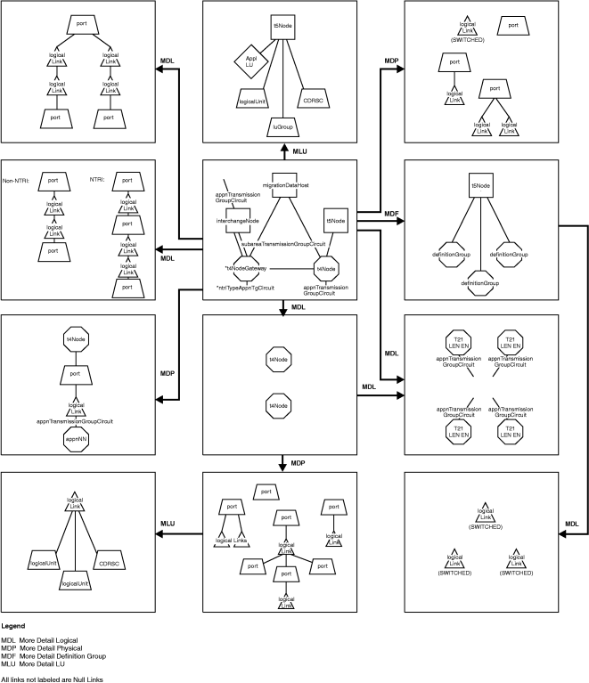
Table 23 describes the subarea views available on an NetView management console. Figure 21 shows the subarea view navigation from the Configuration Backbone view in pictorial form, and Figure 22 shows the Configuration Parents view. Together, Table 23, Figure 21, and Figure 22 help you understand subarea view navigation. All subarea views described are created dynamically.
|
Type of View Possible Objects in View |
Used for: | Reached by: |
|---|---|---|
| Configuration Backbone
appnTransmissionGroupCircuit interchangeNode migrationDataHost *ntriTypeAppnTgCircuit subareaTransmissionGroup t4Node *t4NodeGateway t5Node |
Shows the context of the subarea backbone. See Configuration Backbone View for additional information. | Select one of the resources in this view while in another view and run the Configuration Backbone command; or use the locate resource function. |
| *t4NodeGateway
All the t4Node images (on a network ID basis) of the same physical gateway NCP. No connectivity is shown. |
Indicates the status of the NCP on a NETID basis. | Choose More Detail on a t4Node that represents a gateway NCP. |
| t4Node (Physical)
logicalLink port |
Shows all logicalLink and port objects that are local to this
NCP for a single network ID. Switched links are also shown when they
are in active session using t4Node resources.
If sample FLBTRDMJ is loaded, the view is different. Refer to Creating Port Aggregate Objects Using Sample FLBTRDMJ for more information. |
Choose More Detail (physical) on a non-gateway t4Node |
| t4Node (Logical)
appnEN appnTransmissionGroupCircuit *ntriTypeAppnTgCircuit lenNode t2-1Node |
Shows node (non-network, interchangeNode, migrationDataHost) and circuit objects that are local (LEN or Advanced Peer-to-Peer Networking connected) to this NCP for a single network ID. See t5Node or t4Node More Detail (Logical) View for additional information. | Choose More Detail (logical) on a non-gateway t4Node |
| logicalLink
crossDomainResource logicalLink logicalUnit |
Shows all logicalUnits and crossDomainResources that reside at a logicalLink, and are in RODM. | Choose More Detail on a logicalLink that is reported by a VTAM® topology agent |
| subareaTransmissionGroupCircuit
logicalLink port |
Shows all of the underlying resources of a subareaTransmissionGroupCircuit object. All links in this view are null links. See Subarea Transmission Group Circuit Views for additional information. | Choose More Detail on a subareaTransmissionGroupCircuit object |
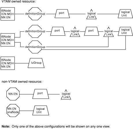
| Configuration Parents
The resource selected, the owning node, and only those other resources that play a part in the configuration. All links shown are null links. |
Displays the configuration of a resource, not the entire connectivity,
to the owning node.
View applicable for both Advanced Peer-to-Peer Networking and subarea. For a VTAM resource, this includes the definitionGroups and the owning VTAM nodes that play a part in the resource configuration. See Configuration Parents View for additional information. |
Issue Locate Resource or from the context menu of a resource in a view select Configuration→ Parents. |
| t5Node (Physical)
logicalLink port |
Shows all logicalLink and port resources that are local to
the t5Node, including switched links even if the link is in session
using t4Node.
If sample FLBTRDMJ is loaded, the view is different. Refer to Creating Port Aggregate Objects Using Sample FLBTRDMJ for more information. |
Choose More Detail (physical) on a t5Node object |
| t5Node (Logical)
appnEN appnTransmissionGroupCircuit *appnTransGroupCircuitCN lenNode t2-1Node |
Shows the LEN or Advanced Peer-to-Peer Networking connected resources (non-network nodes, interchangeNode, migrationDataHost) that are attached to the t5Node. See t5Node or t4Node More Detail (Logical) View for additional information. | Choose More Detail (logical) on a t5Node object |
| t5Node (LUs)
appnEN appnNN crossDomainResource interchangeNode logicalUnit luGroup migrationDataHost t5Node or snaNode |
Shows the LU or LU-like images of objects that reside at a VTAM node and are in RODM.
The t5Node in the view can be an snaNode when the network-qualified CP name is known, but the SNA topology manager cannot determine the type of node. |
Choose More Detail (LU) on a VTAM node object
Note:
A VTAM node can be an appnEN, appnNN,
interchangeNode, or migrationDataHost and a t5Node. |
| t5Node (definitionGroups)
appnEN appnNN definitionGroup interchangeNode migrationDataHost t5Node |
Shows the definitionGroups that have been reported by the VTAM node. | Choose More Detail (definition group) on a VTAM node object |
| definitionGroup
crossDomainResourceManager logicalLink crossDomainResource logicalUnit |
Shows all resources that are a part of a SWITCHED, CDRM, LCLNONSNA, CDRSC, or APPL definitionGroup only. Other types of definitionGroups are not supported. | Choose More Detail (logical) on a definitionGroup object |
| *ntriTypeAppnTgCircuit of appnTransmissionGroupCircuit
appnEN appnNN appnTransmissionGroup interchangeNode lenNode logicalLink migrationDataHost port t2-1Node t4Node *t4NodeGrateway t5Node virtualRoutingNode |
Shows an Advanced Peer-to-Peer Networking connection
to a t5Node or composite node (combination of a VTAM and one or more NCPs), using NTRI-like resources.
NTRI-like resources include NTRI, FrameRelay, Ethernet, NPSI, and ESCON®.
See *ntriTypeAppnTgCircuit View for additional information. |
Choose More Detail on a *ntriTypeAppnTgCircuit |
| *appnTransGroupCircuitCN of appnTransmissionGroupCircuit
appnEN appnNN appnTransmissionGroup interchangeNode lenNode migrationDataHost *ntriTypeAppnTgCircuit subareaTransmissionGroupCircuit t2-1Node t4Node *t4NodeGateway t5Node virtualRoutingNode |
Shows the underlying subarea network that provides the connection
between the interchangeNode or t5Node and the Advanced Peer-to-Peer Networking node on the
other side of the link.
See *appnTransGroupCircuitCN View for additional information. |
Choose More Detail on an *appnTransGroupCircuitCN object where at least one side of the link is a composite node or t5Node |
Figure 21 shows two subareaTransmissionGroupCircuit views in the subarea navigation example. The view at the top left of the figure is presented when you choose More Detail on a selected subareaTransmissionGroupCircuit object that contains the underlying multipoint resources for a single multipoint link that support subareaTransmissionGroupCircuits. The view directly beneath it is presented when you choose More Detail on a selected subareaTransmissionGroupCircuit object that contains underlying resources that are not multipoint resources.
All links in these views are null links.
For non-NTRI-like subareaTransmissionGroupCircuits, each port-logicalLink pair represents one side of the subareaTransmissionGroupCircuit. The port object represents the adapter card that the physical line is attached to, and the logicalLink object represents the link station. If the logicalLink is a VTAM-reported object, the logicalLink represents a PU statement in a VTAMLST member.
If NTRI or NTRI-like objects (FrameRelay, Ethernet, NPSI, or ESCON resources) are part of this subareaTransmissionGroupCircuit, both the logical and physical parts of the line are displayed. This is represented by a double pair of ports and logicalLinks. The pair that is closest to the logicalLink-logicalLink connection is the logical pair that represents the one of many logical resources that traverse this single physical connection. The pair farthest away is the physical pair that represents the physical NTRI, FrameRelay, Ethernet, NPSI, or ESCON connection.
The subareaTransmissionGroupCircuit view for multipoint resources shows, as an example, only the underlying resources for a single multipoint link. The other subareaTransmissionGroupCircuit view shows, as an example, one group of non-NTRI objects and one group of NRTI objects; there can be 2 to 255 groups of these objects.
If the SNA topology manager has only received one perspective of the subareaTransmissionGroupCircuit, only half of the objects are shown in this view. The dividing line is where the two logicalLinks directly connect to each other. For example, if the objects that make up a subareaTransmissionGroupCircuit are owned by two different VTAM nodes and one VTAM node has agent function and the other does not, the SNA topology manager only receives one perspective of the link. Only one side of the logicalLink-logicalLink connection is shown in this case.
Subarea navigation does not have a specific starting point like Advanced Peer-to-Peer Networking, but the Configuration Backbone View (shown in Figure 21 and Figure 24) and the Configuration Parents view are excellent reference views to begin subarea navigation.
Although the purpose of the Configuration Backbone view is to show the context of the subarea backbone, Advanced Peer-to-Peer Networking resources that directly connect to subarea backbone resources are shown in this view. This includes only appnTransmissionGroupCircuits and *ntriTypeAppnTgCircuits that connect to appnNNs or virtualRoutingNodes. It does not include the node on the other side of the link. Choose More Detail on these appnTransmissionGroupCircuit and *ntriTypeAppnTgCircuit objects to navigate to Advanced Peer-to-Peer Networking.
If the Advanced Peer-to-Peer Networking nodes are included, the entire Advanced Peer-to-Peer Networking subnetwork is pulled into this view. The obvious clutter is probably unwanted.
VTAM nodes having a dual image are shown in this view (that is, migrationDataHost nodes and interchangeNodes). Dual-image objects are those that are included in both Advanced Peer-to-Peer Networking and subarea topology status collection. See Figure 9 for a pictorial example.
This view shows the peripheral connectivity of a resource, and the owning node. It does not show the subarea backbone connectivity because the information to determine exactly which intermediate resources (NCPs and subarea TGs) play a role in the connectivity is not known.
The Configuration Parents view is supported for both subarea and Advanced Peer-to-Peer Networking resources. Most VTAM-reported resources include the major nodes (definitionGroups) and the owning VTAM nodes that play a part in the configuration of a resource.
Figure 22 shows examples of possible configurations that can be displayed in the Configuration Parents view. Only one of these groups of resources that are connected is shown in any one view. If you select an object somewhere in the middle and request a Configuration Parents view, only the object requested and the higher-level resources to the owning node are shown.
In the configuration examples shown in Figure 22, all links are null links. Only one of the configuration examples is shown in a Configuration Parents view. The following list includes a description of each configuration example:
If this configuration represents one that involves NTRI or NTRI-like resources (FrameRelay, Ethernet, NPSI, and ESCON), the symbols and what they represent (from left to right) are shown in the following list:
If a Locate Resource is performed, or a Configuration Parents is performed on one of the following resources in a view, then the Configuration Parents view is displayed, with no higher-level resources connected:
The NetView Configuration Children view shows the peripheral connectivity of a resource, and any child nodes. It does not show the subarea backbone connectivity because the information to determine exactly which intermediate resources (NCPs and subarea TGs) play a role in the connectivity is not known.
The Configuration Children view is supported for both subarea and Advanced Peer-to-Peer Networking resources. Most VTAM-reported resources include the major nodes (definitionGroups) and the child VTAM nodes that play a part in the configuration of a resource.
You can perform the Configuration Children function on any of the following listed objects. If an object does not have any children defined, only the selected resource is displayed in the view:
Custom views can contain SNA subarea and Advanced Peer-to-Peer Networking resources managed by SNA topology manager. Custom views can be created using RODM Collection Manager, Visual BLDVIEWS, or BLDVIEWS. For more information on creating custom views, see the IBM Tivoli NetView for z/OS Resource Object Data Manager and GMFHS Programmer’s Guide.
This section contains the views that are the interconnection between Advanced Peer-to-Peer Networking and subarea networks. These views show the Advanced Peer-to-Peer Networking and subarea resources that touch at the periphery of each network and provide a navigation path between the subarea and Advanced Peer-to-Peer Networking.
Table 24 describes the views that contains both Advanced Peer-to-Peer Networking and subarea topology resources available on the NetView management console. The different view navigations in pictorial form are shown in:
|
Type of View Possible Objects in View |
Used for: | Reached by: |
|---|---|---|
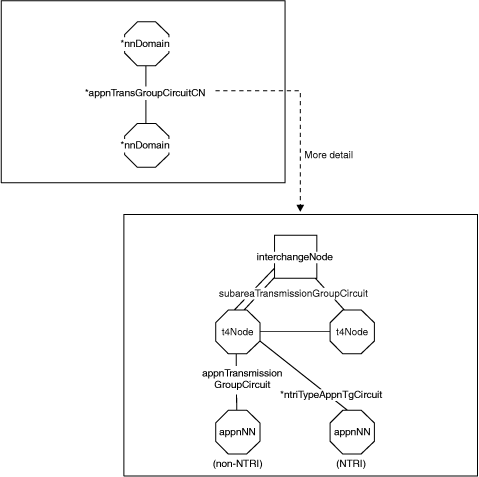
| *interdomainCircuit
*appnTransGroupCircuitCN *nnDomain |
Shows the underlying objects to the *interdomainCircuit. See *interdomainCircuit View for additional information. | Select More Detail for a selected *interdomainCircuit that spans two Advanced Peer-to-Peer Networking subnetworks with at least one of the nodes being a composite node. |
| *appnTransGroupCircuitCN of appnTransmissionGroupCircuit
appnEN appnNN appnTransmissionGroup interchangeNode lenNode migrationDataHost *ntriTypeAppnTgCircuit subareaTransmissionGroupCircuit t2-1Node t4Node *t4NodeGateway t5Node virtualRoutingNode |
Shows the underlying subarea network that provides the connection
between the interchangeNode or t5Node and the Advanced Peer-to-Peer Networking node on the
other side of the link.
See *appnTransGroupCircuitCN View for additional information. |
Select More Detail for a selected *appnTransGroupCircuitCN object where at least one side of the link is a composite node or t5Node. |
| Configuration Parents
All objects |
Shows all objects |
Issue Locate Resource or from the context menu of a resource in a view select Configuration→Parents. |
| Configuration Backbone
appnTransmissionGroupCircuit interchangeNode migrationDataHost *ntriTypeAppnTgCircuit subareaTransmissionGroup t4Node *t4NodeGateway t5Node |
Shows the context of the subarea backbone. The appnTransmissionGroupCircuits are to appnNNs or virtualRoutingNodes. See Configuration Backbone View for additional information. | Issue Locate Resource for a resource that is contained in a Configuration Backbone view, or while in another view, select a resource (one that is in a Configuration Backbone view) and run the Configuration Backbone command. |
| Configuration Children
crossDomainResource logicalLink logicalUnit port |
Shows the child resources of a selected object. See Configuration Children View for additional information. |
Issue Locate Resource, or while in another view, select a resource (one that is in a Configuration Children view) and run the Configuration Children command. |
| *ntriTypeAppnTgCircuit of appnTransmissionGroupCircuit
appnEN appnNN appnTransmissionGroup interchangeNode lenNode logicalLink migrationDataHost port t2-1Node t4Node *t4NodeGateway t5Node virtualRoutingNode |
Shows an Advanced Peer-to-Peer Networking connection
to a t5Node or composite node (combination of a VTAM and one or more NCPs), using NTRI-like resources.
NTRI-like resources include NTRI, FrameRelay, Ethernet, NPSI, and ESCON.
See *ntriTypeAppnTgCircuit View for additional information. |
Select More Detail for a selected *ntriTypeAppnTgCircuit object. |
| t5Node or t4Node (Logical)
appnEN appnTransmissionGroupCircuit *appnTransGroupCircuitCN lenNode t2-1Node |
Shows the LEN or Advanced Peer-to-Peer Networking connected resources (non-network nodes, interchangeNode, migrationDataHost) that are attached to the t5Node or t4Node. The appnTransmissionGroupCircuits are to t2-1Nodes, lenNodes, or appnENs. See t5Node or t4Node More Detail (Logical) View for additional information. | Select More Detail (logical) for a selected t5Node or t4Node object. |
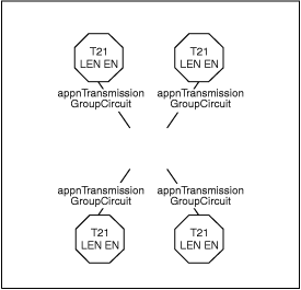
Figure 23 shows the *interdomainCircuit and the *appnTransGroupCircuitCN views that show the interconnection between Advanced Peer-to-Peer Networking and subarea.
Figure 23 shows in the *interdomainCircuit view at least one of the nodes on each side of the link is a composite node, that is, a combination of a VTAM node that has appnNN capabilities, and one or more NCPs. The *appnTransGroupCircuitCN represents the potential t4Nodes or *t4NodeGateways and subareaTransmissionGroupCircuits that the Advanced Peer-to-Peer Networking connection is spanning.
Figure 23 shows in this view two t4Nodes and four subareaTransmissionGroupCircuits. This is an example; any number of t4Nodes and subareaTransmissionGroupCircuits can be shown.
The interchangeNode can be a t5Node. In this case, the purpose of the view is to show the intermediate t4Nodes (or *t4NodeGateways) and subareaTransmissionGroupCircuits between this t5Node and the node on the other side of the LEN connection.
All subareaTransmissionGroupCircuits, and t4Nodes that provide a potential path for the Advanced Peer-to-Peer Networking connection are displayed. The exact path is unknown.
If the appnTransmissionGroupCircuit is using an NTRI or NTRI-like connection to the t4Node, the *ntriTypeAppnTgCircuit link object is shown instead of the appnTransmissionGroupCircuit; this is marked in the example view with NTRI. If the appnTransmissionGroupCircuit is not using an NTRI or NTRI-like connection, only the appnTransmissionGroupCircuit link object is used; this is marked in the example view with Non-NTRI. One, and only one, of these link connection objects is shown in this view.
The appnNN in this figure, can also be an appnEN, interchangeNode, lenNode, migrationDataHost, t2-1Node, t5Node, or virtualRoutingNode.
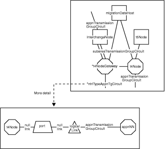
Figure 24 shows the configuration backbone view and the *ntriTypeAppnTgCircuit of appnTransmissionGroupCircuit view that shows the interconnection between Advanced Peer-to-Peer Networking and subarea.
Figure 24 shows that the port and logicalLink in this view are the physical objects that represent the NTRI-like resources. The logical objects are not shown in this view, but can be viewed by selecting the appnTransmissionGroupCircuit and choosing More Detail.
The appnNN object in the view can be:
The t4Node can be a *t4NodeGateway if the NCP is functioning as a gateway.
Figure 25 is the t5Node or t4Node More Detail (logical) view that shows the connections to the Advanced Peer-to-Peer Networking network from a t5Node or t4Node object.
In Figure 25, the t5Node or t4Node is not displayed because the selected object cannot be carried into the next view for a More Detail (logical) command.
Only resources connected to Advanced Peer-to-Peer Networking that are directly attached to the node are displayed. This includes the appnTransmissionGroupCircuit and the node that is on the other side. For t5Nodes, the Advanced Peer-to-Peer Networking resources are restricted to LEN resources only.
If the selected node is a t5Node and any LEN-connected resources through one or more t4Nodes are shown in the view, an *appnTransGroupCircuitCN and the node on the other side are included in the view.
If the selected node is a t4Node and any resources connected to Advanced Peer-to-Peer Networking that are using NTRI or NTRI-like resources are shown in the view, an *ntriTypeAppnTgCircuit and the node on the other side are included in the view.
[ Top of Page | Previous Page | Next Page | Contents ]