UI types in ENI
You can use UI types in IBM® Engineering Lifecycle Optimization - Engineering Insights (ENI), and change appearance of an artifact.
About this task
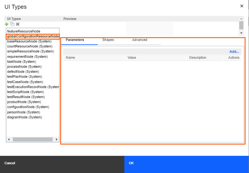
ENI provides UI types to format a node in the view and the formatting is applicable to all nodes in a container. UI type includes definitions that contain different properties such as height, fill color, title, summary, shape. You can use these properties to change the appearance of the nodes. Each node has a UI type that is associated with it.
- Using predefined or system UI type
- Creating a new UI type based on existing UI type
- Creating a new UI type from scratch
- You must define the uri parameter and its value ${uri} to see the required result.
- The uri parameter is a link of the artifact. According to the artifact type, the uri parameter shows a value in the UI type definition. If you edit the value, the container fails to load, and you might not get required result.
Before you begin
- Create a view and name it as UI Types.
- Drag a system artifact element onto the view canvas.
Using predefined or system UI type
About this task
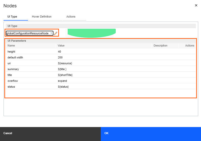
You can use the predefined UI type to format a node. Based on the artifact type, a node consists of a predefined UI type that is assigned to it. UI types are available in the Nodes dialog box.
Procedure
Creating a new UI type based on existing UI type
About this task
Procedure
- Right-click the artifact in the view, and click Edit Node. The Nodes dialog box opens.
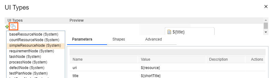
- On the UI Type tab, click the pencil icon that is next to the UI Type list. The UI Type dialog box opens.
- From the UI type list, select the UI type to create a new UI type.
- Click the Duplicate icon to create a copy of the selected UI type.
- In the Add New UI Type window, enter the name or ID for the
new UI type, and click OK. The new UI type appears in the list and the definition of existing UI type is copied to the new UI type.
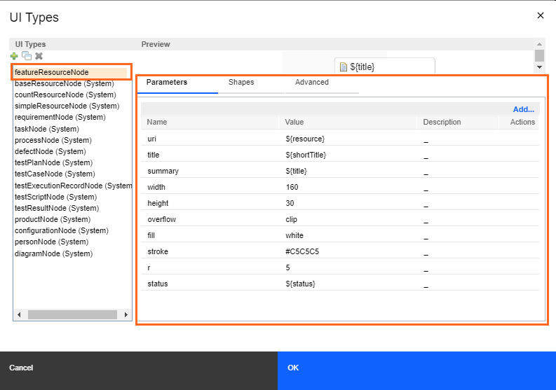
- Change the UI type definition and the parameter values as required, and click OK.
Creating a new UI type from scratch
About this task
Procedure
- Click the Add icon to create a new UI type.
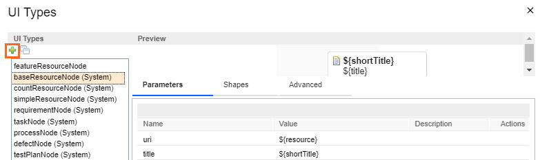
- In the Add New UI Type window, enter the name or ID for the new UI
type, and click OK. The new UI type appears in the list. You can see blank UI type definition.
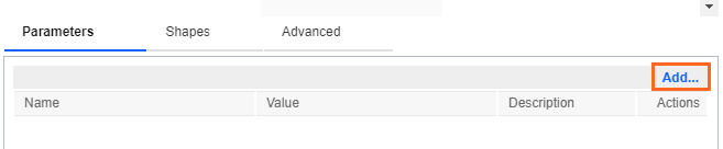
- Click Add… to add parameter in the UI type definition as
required.
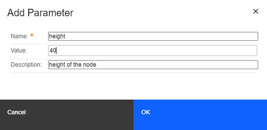
- In the Add Parameter window, specify parameter name and value.
- In the Add Shape window, select the shape type from the Shape
Type list, edit the shape attributes, and then click OK.
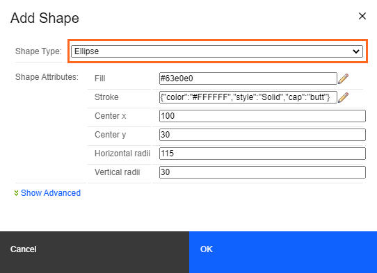
For more information about shape type, see Shape type attributes and description.
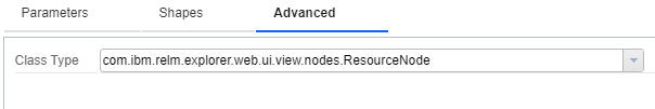
- On the Advanced tab, select the class of the UI type from the
Class Type list, and click OK.
 The new UI type appears in the Nodes dialog box and shows the UI parameters that you defined.