Gateway server (3958 DD6)
The gateway server is the main component of the TS7650G.
The gateway enclosure provides the connections to the customer SAN network (for connection to the client hosts and virtual tape libraries). The server contains several components that are replaceable. These components are field-replaceable units (FRUs) that IBM® service technicians must replace.
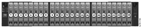
3958 DD6 enclosure front view
Operators (Ops) panel
The enclosure front panel incorporates an Operators (Ops) Panel housed on the left hand mounting flange and connected to the Midplane via a flexible cable. The following illustration shows the controls, LEDs, and connectors on Ops panel.
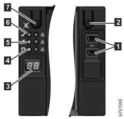
| Item | Description |
|---|---|
| 1 | USB Sockets: Two Mini-B type USB 2.0 sockets, one connected to each controller. |
| 2 | Power Button: The power button can be used
in one of two ways:
|
| 3 | Unit ID Display: Usually displays the enclosure identification number (for use with multiple enclosure systems), but can be configured via VPD. |
| 4 | Logical Fault LED: Amber when there is a fault or change of state from something other than the enclosure management system (usually a disk drive). |
| 5 | Module Fault LED: Amber when there is a system hardware fault. There may also be an associated fault LED on a PCM or controller identifying the faulty component. |
| 6 | System Power LED:
|
| 7 | Input/mute switch: Used in the setting of the LED display. Also used to transition alarm states (although this is dependent on the VPD setup). |
Server rear view (VTL)
- one 3958 DD6 Controller
module equipped with:
- One full height PCIe 2.0
- One low profile PCIe 2.0
- One 1 gigabit (Gb) Ethernet port
- Two Ethernet 1 Gb or 10 Gb ports
- Two 12 Gb mini SAS-HD ports
- Two USB 2.0 ports (rear)
- Onboard 12 Gb SAS (non-RAID)
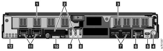
| Item | VTL use | ethX value (if applicable) |
|---|---|---|
| 1 | Emulex 8Gbs Fibre Channel 2.0 - 00WT000
|
|
| 2 | SATA Solid State Drive | |
| 3 | Emulex 8Gbs Fibre Channel 3.0 - LPe15004
|
|
| 4 | Serial Port | |
| 5 | HDMI Connector | |
| 6 | Integrated Management Ethernet Connector | eth2 |
| 7 | Universal Serial Bus Connectors 1 and 2 | |
| 8 | Power On Button | |
| 9 | Reboot Button | |
| 11 | Integrated Ethernet Ports 1 and 2 | eth1 (left) |
| 12 | Post LEDs | |
Server rear view FSI
When configured for FSI, the 3958 DD6 servers are equipped with| Item | FSI (10GB) use | ethX value (if applicable) |
|---|---|---|
| 1 | Emulex 8Gbs Fibre Channel 2.0 - 00WT000
|
|
| 2 | SATA Solid State Drive | |
| 3 | Emulex 8Gbs Fibre Channel 3.0 - LPe15004
|
|
| 4 | Serial Port | |
| 5 | Micro HDMI Connector | |
| 6 | Integrated Management Ethernet Connector | eth2 |
| 7 | Universal Serial Bus Connectors 1 and 2 | |
| 8 | Power On Button | |
| 9 | Reboot Button | |
| 11 | Integrated Ethernet Ports 1 and 2 | eth1 (left) |
| 12 | Post LEDs | |
For more information about the gateway server ports, see Hardware, cabling, and infrastructure responsibilities for the TS7650G.