Replacing a Base or Expansion controller card
 |
CAUTION:
|
Important: Do not replace both the base chassis and the Base Module controller card with
repair components in the same procedure. The firmware does not allow the library to operate if both
components are replaced at the same time. Critical library information is saved in the controller
card and within the chassis. When one is replaced, the data from the original component is
transferred to the repair component. If both the base chassis and Base Module controller are
replaced, you must power cycle the library between component replacements.
Saving the configuration
See Locating Management functions for instructions on saving
configuration settings to a file with the Management GUI or with the Operator Panel. This procedure
is done when a Base Module controller card is replaced, or as an extra precaution when both the
controller card and the module are replaced.
Note: Do not do a Save
Configuration on a library that is in a failed state. Save the configuration on a
working library only.
Powering off the library
Verify that all host processes are idle, then power off the library from the front panel. Depress
Power and hold it for 5 seconds. If the library does not complete a soft
shutdown, depress and hold Power for 10 seconds.
Important: Under
normal circumstances, when the library is powered off by using the front
Power, the robot automatically parks and locks into the Base Module behind
the Operator Panel. If you are given a choice during the power down procedure, choose the default
park position. To protect the spooling cable or other sensitive parts, the accessor must be
in the Base Module before any modules or drives are removed from the library. If it is not, follow
the procedure for returning the accessor to the base module. See Returning the accessor to the Base Module.
Removing the controller card
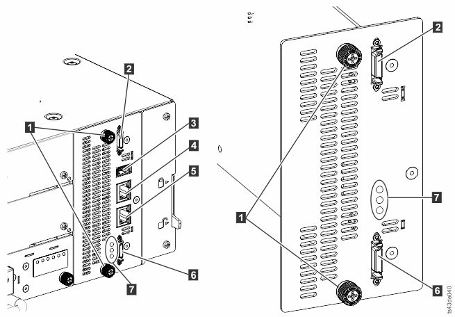
Note: The base controller card is on the left, and the expansion controller card is on the
right.
| 1 | Blue captive thumbscrews |
| 2 | Upper Expansion Module connection port |
| 3 | USB Port |
| 4 | Ethernet Port A |
| 5 | Ethernet Port B |
| 6 | Lower Expansion Module connection port |
| 7 | Controller card LEDs, top to bottom
|
- Unplug the AC power cables from the module that contains the failed controller card.
- On the module that contains the failed controller card, remove the expansion interconnect cables (2 and 6) that connect to other modules, if present.
- Remove the Ethernet cables (4 and 5) and the USB cable (3), if present. (An Expansion Module does not have Ethernet or USB ports. See Figure 1).
- Loosen the two blue captive thumbscrews (1) on the controller.
- Using the thumbscrews, slowly remove the controller from the module.
Installing the Base or Expansion controller card
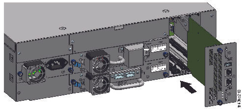
Important: Base and Expansion Module controller cards are keyed to fit in their
respective modules only. A Base Module controller card does not fit into an Expansion Module,
and vice versa. If you encounter resistance when the controller card is installed, make sure that
you are installing the controller card into the appropriate module.
- Position the new controller card on the alignment rails.
- Slide the controller card slowly into the module until it is flush with the back panel of the module.
- Tighten the blue captive thumbscrews (1) with your fingers to secure it to the module.
- Replace the expansion interconnect cables (2 and 6), the Ethernet cable or cables (4 and 5), and the USB cable (3) that were removed previously. (An Expansion Module does not have Ethernet or USB ports. See Figure 1).
- Plug in the AC power cables.
Powering on the library
Power on the library by pressing Power on the Base Module just below the Operator Panel. The green light illuminates. When the library is powered on, it inventories the tape cartridges in the magazines, checks the firmware version on all modules, and configures the tape drives. Then, the library confirms the presence of the existing modules, and searches for any new modules.
Verifying the Base or Expansion controller card
- Verify that the library has the most up-to-date firmware revision. To find the version of firmware that is installed on the library, check the Library Properties page of the Management GUI or the page of the Operator Panel.
- If the Base Module controller is replaced, upgrade the firmware if necessary. Update the
firmware from the Management GUI at . Important: If you are asked whether to retain the serial number, always select Yes.
- Check the Attention light on the front panel and login to web interface and check the dashboard for any alerts.
- With the Operator Panel or the Management GUI, check for any events. The event that indicated that the controller was faulty is cleared.
- If the base module controller is replaced, the library configuration is automatically restored. Validate the library configuration, and complete a Restore if the library configuration was not restored.
- If the UID LEDs are still illuminated, deactivate them by using the Operator Panel or Management GUI.
- Resume the host applications.