subscribe iconSubscribe to this information
POWER7 information

Removing and replacing a PCI adapter contained in a cassette in a Linux partition that is powered on

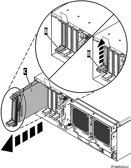
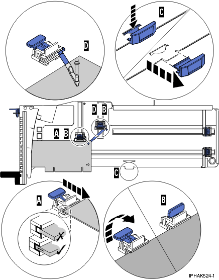
Procedures performed on a PCI adapter in a Linux partition that is powered on, also known as hot-plug procedures, require the system administrator to take the PCI adapter offline prior to performing the operation. Before taking an adapter offline, the devices attached to the adapter must be taken offline as well. This action prevents a service representative or user from causing an unexpected outage for system users.

Before performing this procedure, do the following steps:

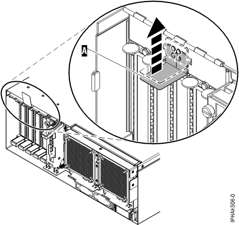
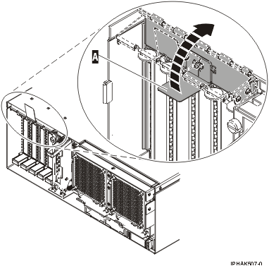
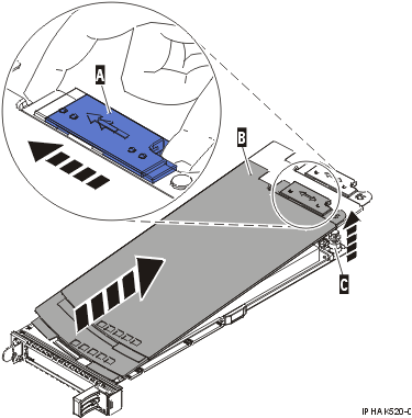
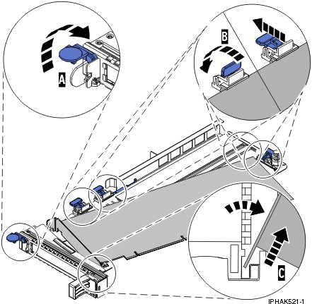
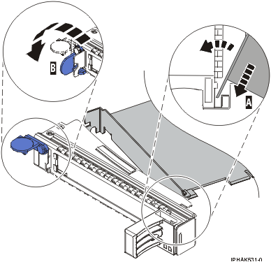
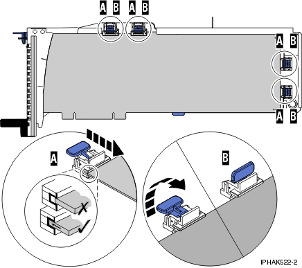
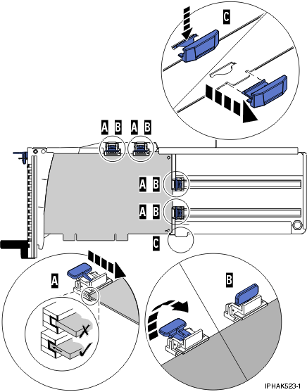
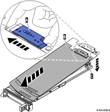
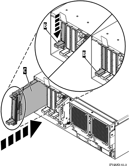
To remove and replace an adapter, do the following steps:

  1. Determine the location of the PCI adapter in the system.
  2. Record the slot number and location of each adapter being removed. Adapter slots are numbered on the rear of the system unit.
  3. Ensure that any processes or applications that might use the adapter are stopped.
  4. Run the drmgr -c pci command to enable an adapter to be replaced:
    For example, to replace the PCI adapter in slot U7879.001.DQD014E-P1-C3 run this command:
    drmgr -c pci -r -s U7879.001.DQD014E-P1-C3

    Follow the instructions on the display to complete the task.

  5. Label, and then disconnect all cables attached to the adapter you plan to remove.
  6. Lift up on the PCI adapter EMC shield (A) as shown in Figure 1 and then rotate it up and away from the cassette as shown in Figure 2.

    If the PCI adapter does not have an EMC shield, go to step 7.

    Figure 1. Lift up on the EMC shield
    Lift up on the EMC shield.
    Figure 2. Rotate the EMC shield into the open position
    Rotate the EMC shield into the open position
  7. Remove the cassette. Lift up the lower cassette handle (B) as shown in the following figure. Pull the PCI cassette (C) out of the system.
    Attention: A cassette containing either a PCI adapter or filler panel must be placed in the PCI adapter slot of the system unit for proper air flow and cooling.
    Figure 3. PCI adapter cassette removed from the system unit
    PCI adapter removed from the system unit.
  8. Place the cassette with the cover facing up on an approved ESD surface. The cover will have a label on it.
  9. Install the replacement adapter into the PCI adapter cassette by completing the following steps. If the cassette is not going to contain a replacement adapter, use this same procedure to place an adapter filler panel in the cassette.
    1. Remove the cassette cover by doing the following steps:
      1. Slide the cover latch (A) to disengage it from the pivot pin (C) as shown in the following figure.
      2. Lift the cover (B) off of the pivot pin.
      3. Slide the cover off of the cassette.
        Figure 4. PCI adapter cassette cover removed
        PCI adapter single-width cassette cover removed.
    2. Remove the adapter from the cassette by doing the following steps:
      1. Unlock the adapter retainers by rotating the retainer clip (A) into the horizontal position. See Figure 5.
        Notes:
        • The edge of the adapter located at the end of the cassette that contains the cassette handles is called the adapter tailstock.
        • Two retainers are located at the top of the cassette, along the top edge of the adapter. Two more retainers are located at the edge of the cassette opposite of the adapter tailstock.
        • When the retainer clip is in the horizontal position, the adapter retainers are unlocked and can slide away from the card.
        • If the corner support retainer is used, unlock it, and then slide the corner support retainer away from the card.
      2. Push the adapter retainers (B) away from the adapter.
      3. Unlock the adapter tailstock clamp (C).
      4. Rotate the adapter out of the cassette by grasping the edge of the adapter opposite the tailstock, and then firmly rotate the adapter toward the bottom of the cassette.
      5. Lift the adapter out of the tailstock retaining channel.
        Figure 5. Adapter removed from the PCI adapter cassette
        Adapter removed from the PCI adapter single-width cassette.
    3. Place the new adapter in the cassette.
      Attention: A cassette containing either a PCI adapter or filler panel must be placed in the PCI adapter slot of the system unit for proper air flow and cooling. If the cassette is not going to contain a PCI adapter, use this same procedure to place an adapter filler panel in the cassette.
      1. Remove any shipping handles or brackets attached to the adapter.
      2. With the tailstock clamp in the open position, insert the adapter firmly into the tailstock retaining channel (A). See Figure 6.
      3. Rotate the adapter toward the top of the cassette and into place.
      4. Close the tailstock clamp.
        Figure 6. Adapter removed from the PCI adapter single-width cassette
        Adapter removed from the PCI adapter single-width cassette.
      5. Position the adapter retainers to support the adapter, and then rotate the retainer clip (B) into the closed position. See Figure 6.
        Note: Two retainers are located at the top of the cassette, along the top edge of the adapter. Two more retainers are located at the edge of the cassette opposite of the adapter tailstock. When the adapter retainer clip is in the horizontal position, the adapter retainers are unlocked and can slide toward the adapter. Place the retainers on the adapter according to the length of the adapter being used. Select the appropriate instructions:
        Adapter-cassette retainer placement for long adapters
        • Place and lock the retainers (B). See Figure 7.
          Attention: Use of the lower corner support retainer might interfere with the docking of the PCI card when positioned within the system. Ensure the retainer does not interfere with the adapter connectors on the system backplane.
        • Ensure the adapter edge is seated in each retainer groove (A). If the shape of the adapter or the presence of a connector will not allow the adapter edge to be seated into the retainer groove, ensure the retainer is still locked firmly against that edge or connector.
          Figure 7. Long adapter in the PCI adapter cassette with the supports and stabilizer in place
          View of a long adapter in the PCI adapter single-width cassette with the retainers and stabilizer in place.
        Adapter-cassette retainer placement for medium-length adapters
        • Remove the adapter stabilizer (C). See Figure 8.
        • Place and lock the retainers (B).
        • Ensure the adapter edge is seated in each retainer groove (A). If the shape of the adapter or the presence of a connector will not allow the adapter edge to be seated into the retainer groove, ensure the retainer is still locked firmly against that edge or connector.
          Figure 8. Medium-length adapter in the PCI adapter cassette with the supports in place
          View of a medium-length adapter in the PCI adapter single-width cassette with the retainers in place.
        Adapter-cassette retainer placement for short adapters
        • Remove the adapter stabilizer (C). See Figure 9.
        • Place the hookarm (D) into the hole in the corner of the adapter. This supports the card when it is undocked from the connector on the system backplane.
        • Place and lock the retainers (B).
        • Ensure the adapter edge is seated in each retainer groove (A). If the shape of the adapter or the presence of a connector will not allow the adapter edge to be seated into the retainer groove, ensure the retainer is still locked firmly against that edge or connector.
          Figure 9. Short adapter in the PCI adapter cassette with the supports and the hookarm in place
          View of a short adapter in the PCI adapter single-width cassette with the retainers and the hookarm in place.
    4. Replace the cassette cover by doing the following steps:
      1. Slide the cover (B) into position on the cassette.
      2. While holding the cover latch (A) in the open position, place the cover over the pivot pin (C).
      3. Release the cover latch to lock the cover into place.
        Figure 10. PCI adapter cassette cover replaced
        PCI adapter single-width cassette cover replaced.
  10. At the back of the system, lift the cassette cover flap and identify the cassette slot you want to use.
  11. Ensure the lower cassette handle is pressed up toward the retainer clip. This places the adapter in the correct position to be docked in the system.
  12. Lift and hold the PCI adapter EMC shield in the open position. See Figure 1 and Figure 2.
  13. Slide the cassette (C) into the cassette slot as shown in the following figure.
  14. When the cassette is fully inserted into the system, firmly press downward on the lower cassette handle (B) to lock the adapter in its connector.
    Figure 11. PCI adapter cassette removed from the system unit
    PCI adapter placed into the system unit.
  15. Connect the adapter cables.
  16. Lower the PCI adapter EMC shield (A) into the closed position, close the shield latch, then close the rear rack door.
    Figure 12. PCI adapter EMC shield in the closed position
    PCI adapter EMC shield in the closed position.
  17. Run the lsslot command to verify that the slot is occupied.

    For example, Enter lsslot -c pci -s U7879.001.DQD014E-P1-C3

    The following is an example of the information displayed by this command:

    # Slot     Description      Device(s) U7879.001.DQD014E-P1-C3 PCI-X capable,
    64 bit, 133MHz slot 0001:40:01.0


Send feedback Rate this page

Last updated: Fri, March 20, 2015