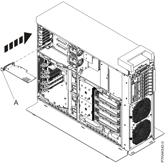
Replace a PCI adapter with the system power off.
You must have already completed the procedure Removing a PCI adapter from the 8202-E4B, 8202-E4C, 8202-E4D, 8205-E6B, 8205-E6C, or 8205-E6D with the power off to have the slot that is powered
off.
If your system is managed by an HMC, use the HMC to complete the steps
for replacing the part in the system. For instructions, see Replacing a part by using the
HMC.
Note: Check the display
on your control panel to see if your system is managed by the HMC. If you do not see HMC displayed,
your system has never been connected to the HMC. A display of HMC=0 indicates
that your system does not currently have the HMC. If the HMC display equals a number
greater than 0, your system has the HMC.
If you
do not have an HMC,
complete the following steps to replace a PCI adapter with the system
power off:
- Complete the prerequisite tasks that
are described in Before you
begin.
- Take appropriate precautions for avoiding
electric shock and handling static-sensitive devices. For
information, see Avoiding electric shock and Handling static-sensitive devices.
- Stop the system or logical partition. For
instructions, see Stopping a
system or logical partition.
- If your system is a rack-mounted system, place the system
into the service position. For instructions, see Placing
a rack-mounted model into the service position.
- Remove the service access cover.
- If you are replacing a failing PCI adapter, use the service
label on the service access cover to match the failing part with its
location code. For instructions, see 8202-E4B, 8202-E4C, 8202-E4D, 8205-E6B, 8205-E6C,
or 8205-E6D locations. Alternatively, use the Advanced System Management Interface
(ASMI) to identify the failing part with its location code. For instructions,
see Setting up and accessing the ASMI.
If you are replacing the PCI adapter for other reasons, continue to
the next step.
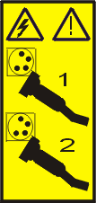
- Reach behind
the system and disconnect all power cords from the unit you are servicing.
Figure 1. Disconnecting the power cords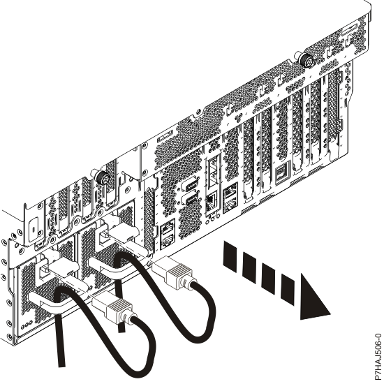
Note: An optional power supply is available in the 8202-E4B, 8202-E4C,
or 8202-E4D system.
The 8205-E6B, 8205-E6C,
or 8205-E6D system
is equipped with a mandatory second power supply. Before continuing
with this procedure, ensure that the power source to the system has
been disconnected.
(L003)
or
- Attach the wrist strap.
Attention: - Attach a wrist strap to an unpainted metal surface of your hardware
to prevent electrostatic discharge (ESD) from damaging your hardware.
- When using a wrist strap, follow all electrical safety procedures.
A wrist strap is for static control. It does not increase or decrease
your risk of receiving electric shock when using or working on electrical
equipment.
- If you do not have a wrist strap, just before removing the product
from ESD packaging and installing or replacing hardware, touch an
unpainted metal surface of the system for a minimum of 5 seconds.
- If necessary, remove the new adapter from the antistatic
package.
Attention: Avoid
touching the components and gold connectors on the adapter.
- Place the adapter, component-side up, on a flat, static-protective
surface.
Note: Some PCI adapters are shipped from the manufacturer
with a blue handle or support bracket along the back edge of the card.
To use adapters of this type in this system, you must remove the blue
handle or support bracket from the card.
Attention: A pin on the tailstock of the adapter
resembles a removable screw. Do not remove this pin. It is required
for correct alignment and seating.
- Remove the adapter that you want to replace. For instructions,
see Removing a PCI adapter from the 8202-E4B, 8202-E4C, 8202-E4D, 8205-E6B, 8205-E6C, or 8205-E6D with the power off.
- If necessary, remove the adapter expansion slot filler.
- If the target slot’s
adapter latch (B) is not already in the open
position, pull the latch into the open position by pressing down on
it from its clip on the back of the system.
Note: If you
are installing a PCI adapter on the expansion riser, there is no adapter
latch.
- Carefully grasp the new adapter by its tailstock (A),
and align the adapter with the expansion slot and its connector on
the system backplane.
- Press the adapter firmly into its connector.
Attention: When you install an adapter into
the system, be sure that it is completely and correctly seated in
its connector.
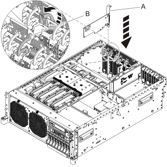
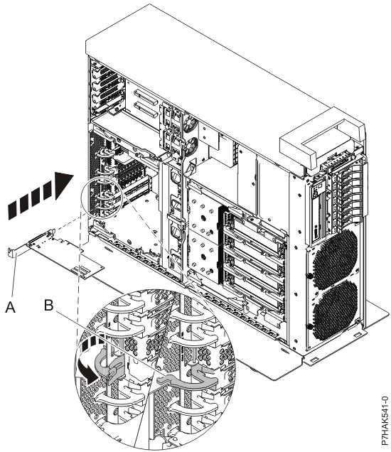
- Pull the adapter latch (B) back
into place, as shown in Figure 2 and Figure 3.
Figure 2. Replacing a PCI
adapter in a rack-mounted system unit
Figure 3. Replacing a PCI
adapter in a stand-alone system unit
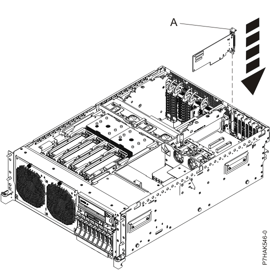
- If your system has an expansion riser, you can press the
low profile PCI adapter into its slot. Guide it into position by its
tailstock (A) and then press the adapter into
its slot, as shown in Figure 4 and Figure 5.
Figure 4. Replacing
a PCI adapter in an expansion riser in a rack-mounted system
Figure 5. Replacing
a PCI adapter in an expansion riser in a stand-alone system
- Connect the adapter cables.
- If you are servicing a rack-mounted system, route the cables
through the cable-management arm.
- Replace or close the service access
cover.
- For a rack-mounted system, place the system into the operating
position. For instructions, see Placing
a rack-mounted model into the operating position.
- Reconnect the power source to the system.
- Start the system or logical partition. For instructions, see Starting a system or logical partition.
- Verify the installed part.
- If you replaced the part because of a service action, verify the
installed part. For instructions, see Verifying a repair.
- If you installed the part for any other reason, verify the installed
part. For instructions, see Verifying the installed part.


