Server specifications provide detailed information for your server, including dimensions, electrical, power, temperature, environment, and service clearances.
| Model | Description | Minimum per system | Maximum per system |
|---|---|---|---|
| FC 57701 | 42 EIA unit, 24-inch rack (60-inch deep) | 1 | 1 |
| FC 5798 | PCI-X I/O drawer (4U) | 0 | 4 |
| FC 68722 | Water cooling option | 1 | 1 |
| FC 6874 | Slimline doors (front and rear) with integrated rear heat exchanger | 0 | 1 |
| FC 6875 | Acoustic doors (front and rear) with integrated rear heat exchanger | 0 | 1 |
| FC 7298 | 32-core, 4.7 GHz, POWER6® processor (2U) | 1 | 14 |
1 The customer must choose between either acoustical doors or slimline doors during the order process. Slimline doors take up slightly less floor space in front of the rack but provide no noise reduction and generally do not meet industry acoustical noise limits. See Doors and covers for model 9125-F2A. 2 Maximum water coolant contained in a rack of 12 CEC drawers and 1 disk enclosure: 100 liters (26.5 gallons). |
|||
| Dimensions | Slimline doors | Acoustical doors |
|---|---|---|
| Height | 2013 mm (79.5 in.) | 2013 mm (79.5 in.) |
| Width | 785 mm (30.9 in.) | 785 mm (30.9 in) |
| Depth | 1785 mm (70.3 in.) | 1939 mm (76.3 in.) |
| 1The front and rear doors are shipped separately from the rack assembly. | ||
| Maximum total system weight |
|---|
| 1680 kg (3703 lb) |
| For configuration weight, see Approximate system weights by configuration. |
| Electrical and thermal characteristics | Properties | ||
|---|---|---|---|
| Rated voltage and frequency | 200 - 240 V ac at 50 - 60 Hz | 380 - 480 V ac at 50 - 60 Hz | |
| Rated current (Amps) | 100 A | 60 A | |
| Power consumption | See Total system power consumption | ||
| Typical power factor | 0.99 | 0.96 | 0.96 |
| Thermal output1 | |||
| Dual power feature code | Standard | ||
| Branch circuit breaker and cord | See Breaker rating and cord information | ||
| 1Power draw and heat load vary greatly by configuration. When planning for an electrical system, it is important to use maximum values. However, when planning for heat load, you can use the IBM® Systems Energy Estimator to obtain a heat output estimate based on a specific configuration. See The IBM Systems Energy Estimator Web site for more information. | |||
| BPR number | 208 V ac amperage | 208 time (micro seconds) | 480 V ac amperage | 480 time (micro seconds) |
|---|---|---|---|---|
| Zero | 100 | 20 | 120 | 20 |
| One | 110 | 150 | 140 | 150 |
| Two | 140 | 150 | 170 | 150 |
| Three | 170 | 150 | 210 | 150 |
| Four | 200 | 150 | 250 | 150 |
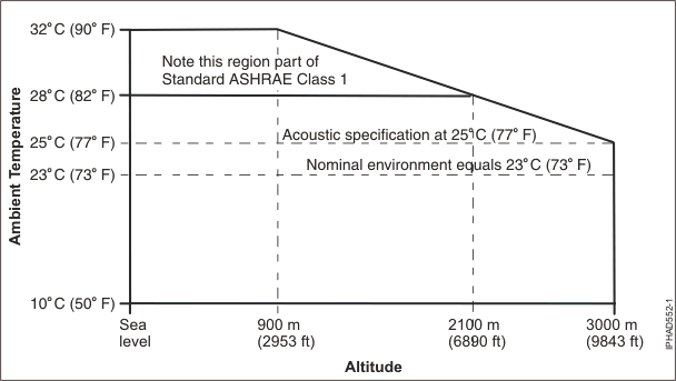
The environment must adhere to all American Society of Heating, Refrigerating and Air-Conditioning Engineers (ASHRAE) class 1 specifications except for operating temperature range and the wet bulb temperature. The maximum allowable operating temperature is reduced for altitudes above 4250 feet as shown in the Operating inlet air temperature versus elevation graphic.
| ASHRAE | Class 1 (Except for temperature range) | |||
|---|---|---|---|---|
| Operating temperature (maximum inlet (Dry bulb) (0 - 2100 m (0 - 6890 ft) altitude) | 10 - 28°C (50 - 82.4°F) | |||
| Nonoperating temperature | 10 - 43°C (50 - 109°F) | |||
| Storage temperature | 1 - 60°C (34 - 140°F) | |||
| Shipping temperature | -40 - 60°C (-40 - 140°F) | |||
| Maximum altitude | 3000 meters (9843 ft) | |||
| Operating | Nonoperating | Storage | Shipping | |
| Noncondensing relative humidity | 20 - 80% | 20 - 80% | 5 - 80% | 5 - 100% |
1When an IBM-approved vapor bag and desiccant packets are used to protect the system, the storage specifications are valid for 6 months and the shipping specifications are valid for 1 month. Otherwise, storage and shipping specifications are valid for 2 weeks each. 2The upper limit of the dry bulb temperature must be derated above 2100 m (6890 ft), as is shown in Operating inlet air temperature versus elevation. The maximum altitude is 3000 m (9843 ft). |
||||
| Product configuration | Declared A-Weighted Sound Power Level, LWAd (B) | Declared A-Weighted Sound Pressure Level, LpAm (dB) | ||
|---|---|---|---|---|
| Operating | Idling | Operating | Idling | |
| Typical configuration with acoustical door set: seven processor nodes, two modular water units, and one bulk power assembly. All air moving devices at nominal speeds. | 8.2 4 | 8.2 4 | 65 | 65 |
| Typical configuration with nonacoustical (slimline) door set: seven processor nodes, two modular water units, and one bulk power assembly. All air moving devices at nominal speeds. | 8.5 | 8.5 | 68 | 68 |
| Maximum configuration with acoustical door set: fourteen processor nodes, two modular water units, and one bulk power assembly. All air moving devices at nominal speeds. | 8.75 | 8.75 | 70 | 70 |
| Maximum configuration with nonacoustical (slimline) door set: fourteen processor nodes, two modular water units, and one bulk power assembly. All air moving devices at nominal speeds. | 8.95 | 8.95 | 72 | 72 |
1Declared level LWAd is the upper-limit A-weighted sound power level. Declared level LpAm is the mean A-weighted sound pressure level measured at the 1-meter bystander positions. 2All measurements are made in conformance with ISO 7779 and declared in conformance with ISO 9296. 31 Bel (B) equals 10 Decibels (dB). 4Meets IT Product Noise Limits for, Generally Unattended Data Center, per Statskontoret Technical Standard 26:6. Note: 5 Government
regulations (such as those prescribed by Occupational Safety and Health
Administration (OSHA) or European Community Directives) might govern
noise level exposure in the workplace and might apply to you and your
server installation. This IBM system is available with an optional
acoustical door feature that can help reduce the noise emitted from
this system. The actual sound pressure levels in your installation
depend on a variety of factors, including the number of racks in the
installation, the size, materials, the configuration of the room where
you designate the racks to be installed, the noise levels from other
equipment, the room ambient temperature, and employees' location
in relation to the equipment. Compliance with such government regulations
also depends on a variety of additional factors, including the duration
of employees' exposure and whether employees wear hearing protection.
Consult qualified experts in this field to determine whether you
are in compliance with the applicable regulations.
|
||||
| Front | Back |
|---|---|
| 1549.4 mm (61 in.) | 914.4 mm (36 in.) |
1Service clearances are always referenced off of the side covers or the front and back of the frame, and not the front and back doors. 2There is no side service clearance required next to the frame on either side. 3Side service clearance is required in the front and back of the frame. 4Air flow is from the front of the frame to the back of the frame. 5Note the dimension from the back of the frame to the floor tile grid alignment point. It is extremely important that this point on the frame is aligned properly to the floor tile. It is essential that the weight distribution plates and floor tile cutouts correspond to the features on the base of the frame. |
|

To effectively plan for model 9125-F2A, you need to see the following topics and incorporate the information into your server planning, as appropriate.