 z/OS HCD User's Guide
 z/OS HCD User's Guide
|
Previous topic |
Next topic |
Contents |
Index |
Contact z/OS |
Library |
PDF
Viewing CTC connections z/OS HCD User's Guide SC34-2669-00 |
|||||||||
Viewing CTC connectionsHCD offers you the possibility to view and verify your CTC connections. You can view existing CTC connections including online diagnostic messages on the following lists:
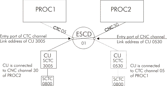
The CTC Connection List lets you immediately verify whether your definitions are done correctly. ESCON channel-to-channel supportAn ESCON CTC connection requires a CTC channel at one end of the connection and a CNC or FCV channel at the other end of the connection. The two channels can be considered as communicating directly with each other in a peer-to-peer fashion. Each channel defines the channel at the other end of the CTC connection as an SCTC control unit. This is illustrated in Figure 67. FICON channel-to-channel supportFCTC support differs from ESCON CTC support not only in the channel types used. The main differences are as follows:
In order to be usable as an FCTC connection channel, a FICON channel path must be defined to an FCTC control unit which is connected to FCTC devices. Figure 67. CTC/CNC connection established using a dynamic connection
 The entry port of the channel at the other end of the CTC connection corresponds to the link address of the control unit representing the channel. The CTC devices associated with the control units at both ends of the CTC connection may have different device numbers, but they must have the same unit address. The device type of both devices must be the same (for example, SCTC or BCTC). Restrictions applying to the CTC Connection List
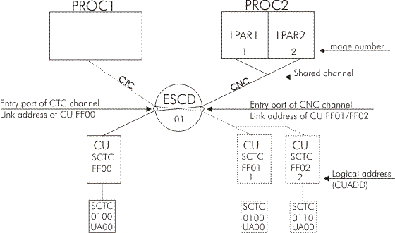
CTC connections with shared channelsIf your processor has MIF support you can share your channels among several partitions to save physical connections. The following figure shows you the case when a CNC channel is shared between two partitions. The CTC channel will need a separate control unit definition for each partition sharing the CNC channel. Each of these control unit definitions has the same destination link address but the control unit logical addresses (CUADD) must be different. The control unit logical address must correspond to the image number of the logical partition. Note:
If the target channel path is non-shared, either you
must not specify a control unit logical address, or its value must
be 0. Figure 68. CTC/CNC connection established using shared channels
 For further specification rules, refer to the IOCP User's Guide for your processor. How to view CTC connectionsYou can use action View related CTC connections (or action code k ) on the following lists:
A panel similar to the following one is displayed: Goto Filter Backup Query Help
------------------------------------------------------------------------------
CTC Connection List Row 1 of 14 More: >
Select CTC connections to view CTC Messages, then press Enter.
-----------CTC or FC side---------- ---------CNC/FCV or FC side--------
/ Proc.CSSID Part. Devices CH CU Proc.CSSID Part. Devices CH CU Msg.
_ PROC001A 0500,5 20 1020 PROC001 0100,5 10 1010 G750
_ PROC001A 0690,1 20 0069 G752
_ PROC002 0650,1 11 0065 PROC002 0660,1 13 0066 G753
_ PROC002 0680,1 11 0068 G752
_ PROC002 0701,1 12 0050 PROC003 PART1 0301,1 10 1012
_ PROC002 0800,5 22 0060 PROC003 PART2 0400,5 11 1013
_ PROC002 0805,1 22 0060 PROC003 PART2 0405,1 11 1013 G751
_ PROC002 0806,3 22 0060 PROC003 PART2 0406,3 11 1013
_ PROC002 2400,1 24 0024 G756
_ XMP1.1 PART1 1105,1 21 0105 PROC001 1106,1 10 0106
_ XMP1.1 PART1 1107,1 21 0107 PROC002 1108,1 26 0108 G750
PROC002 0200,2 10 1011 G757
XMP1.1 PART1 0300,1 10 1012 G754
XMP1.1 PART2 0300,2 10 1012 G754
This panel shows the definitions of the CNC/FCV side in relation to the definitions of the CTC side, such as processor, partition, channel path, control unit, and device information. Incomplete CTC definitionsIf the CTC connection is not correctly defined, the fields on the CTC Connection List can be incomplete and an error message is shown. For example, G754 in column Msg. refers to message CBDG754I, which indicates that HCD cannot determine the connection, because no control units and devices match to the processor, partition, control unit, and device of the same row. Displaying more detailed informationScroll to the right to see more detailed information about the CTC side of the connection, such as channel path mode, switch information, detailed control unit and device information. Goto Filter Backup Query Help
-------------------------------------------------------------------------
CTC Connection List (CTC/FC) Row 1 of 14 More: <>
Select CTC connections to view CTC Messages, then press Enter.
-Partition-- ----Devices----- -CHPID- Entry Dyn Link CU
/ Proc.CSSID Name Num Number Type OS UA ID Mode SW PO SW CU Addr ADD
_ PROC001A 0500,5 BCTC N 00 20 DED 05 F0 05 1020 E120
_ PROC001A 0690,1 SCTC N 00 20 DED 05 F0 05 0069 E728
_ PROC002 0650,1 SCTC N 00 11 DED 05 E7 05 0065 E840
_ PROC002 0680,1 SCTC N 00 11 DED 05 E7 05 0068 F0
_ PROC002 0701,1 SCTC N 01 12 DED 05 D0 05 0050 F4 1
_ PROC002 0800,5 SCTC N 00 22 DED 05 D7 05 0060 F3 2
_ PROC002 0805,1 BCTC N 05 22 DED 05 D7 05 0060 F3 2
_ PROC002 0806,3 SCTC N 06 22 DED 05 D7 05 0060 F3 2
_ PROC002 2400,1 SCTC N 00 24 DED 04 E0 05 0024 E0
_ XMP1.1 PART1 1 1105,1 SCTC N 00 21 DED 05 F7 05 0105 E1
_ XMP1.1 PART2 2 1107,1 SCTC N 00 21 DED 05 F7 05 0107 F8Scroll once again to the right to see the same detailed information for the CNC/FCV side of the connection. Goto Filter Backup Query Help
-------------------------------------------------------------------------
CTC Connection List (CNC/FCV/FC) Row 1 of 14 More: <
Select CTC connections to view CTC Messages, then press Enter.
-Partition-- ----Devices----- -CHPID- Entry Dyn Link CU
/ Proc.CSSID Name Num Number Type OS UA ID Mode SW PO SW CU Addr ADD
_ PROC001 0100,5 BCTC N 00 10 DED 05 E1 05 1010 F0 0
_
_ PROC002 0660,1 SCTC N 00 13 DED 05 E8 05 0066 E7
_
_ XMP1.1 PART1 1 0301,1 SCTC N 01 10 SHR 05 F4 05 1012 D0
_ XMP1.1 PART2 2 0400,5 SCTC N 00 11 SHR 05 F3 05 1013 D7
_ XMP1.1 PART2 2 0405,1 SCTC N 05 11 SHR 05 F3 05 1013 D7
_ XMP1.1 PART2 2 0406,3 SCTC N 06 11 SHR 05 F3 05 1013 D7
_
_ PROC001 1106,1 SCTC N 00 10 DED 05 E1 05 0106 F7
_ PROC002 1108,1 SCTC N 00 26 DED 05 F8 05 0108 F7 1
_ PROC002 0200,2 SCTC N 00 10 DED 1011 C5
_ XMP1.1 PART1 1 0300,1 SCTC N 00 10 SHR 05 F4 05 1012 D0
_ XMP1.1 PART2 2 0300,2 SCTC N 00 10 SHR 05 F4 05 1012 D0
Filtering CTC definitionsTo get a better overview of your CTC connections you can filter the list by specifying different filter criteria. Select action bar Filter and then Set filter. The following panel appears: *-------------------------- Filter CTC Connections ---------------------*
| |
| |
| Specify or revise the following filter criteria and press Enter. |
| |
| Message ID . . . . _____ |
| Device type . . . . ____ (SCTC/BCTC/FCTC) |
| Dynamic switch . . __ + |
| |
| CTC or FC side CNC/FCV or FC side |
| Processor.CSSID . . __________ + Processor.CSSID . . __________ + |
| Partition . . . . . ________ + Partition . . . . . ________ + |
| CHPID . . . . . . . __ CHPID . . . . . . . __ |
| |
| CU number . . . . . ____ CU number . . . . . ____ |
| Starting device no. ____ Starting device no. ____ |
| Defined to OS . . . _ (Y/N) Defined to OS . . . _ (Y/N) |
*-----------------------------------------------------------------------*
Printing CTC connection listsYou can also print the list panel using the SAVE command as described in How to print list panels. Displaying diagnostic messagesSelect one or more CTC connections and press the Enter key to display diagnostic messages for the connections. For each connection, HCD displays one message, even if the connection includes several errors. HCD displays the messages according to the following priority list:
A message list may look as follows. The messages are sorted by severity. Save Query Help
------------------------------------------------------------------------
Message List Row 1 of11
Command ===> __________________________________________ Scroll ===> PAGE
Messages are sorted by severity. Select one or more, then press Enter.
/ Sev Msg. ID Message Text
_ E CBDG750I Logical address (CUADD) is specified for CU 1010,
# but CHPID 20 of processor PROC001A is not defined as
# shared.
_ E CBDG752I Channel path type error. CHPID 20 of processor PROC001A
# is connected to CHPID 11 of processor PROC002 with the
# same type.
_ W CBDG753I Wrap around connection detected for processor PROC002
# (partition - none -) via CHPID 11 and CHPID 13.
_ I CBDG756I HCD cannot determine connection. CHPID 24 of processor
# PROC002 is connected via chained switches.


|
 Copyright IBM Corporation 1990, 2014 Copyright IBM Corporation 1990, 2014 |