Troubleshooting
Problem
Understand Serial ATA (SATA) technology and solve SATA problems
Resolving The Problem
- To begin troubleshooting, check the following top issues. If your issue is listed, select the link; otherwise, proceed to step 2.
- Make sure your system is at the latest level of BIOS. Systems utilizing internal serial ATA (SATA) hard disk drives might experience random blue screens errors when resuming from S3 sleep state. This may apply to systems running Microsoft Windows XP or Windows 2000 Professional.
- Check cable connections. Ensure that the connections on both ends of both the SATA interface connector cable, and the power connector cable are firm and proper. With the SATA interface, each drive has its own cable that connects directly to the Serial ATA host controller. There is no master-slave relationship between drives that use a Serial ATA interface (unlike Parallel ATA). There are no jumpers, terminators, or other settings on SATA drives for proper operation. Properly connecting a SATA hard disk drive:
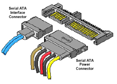
- Locate the signal cable that came with your computer or with the new drive. When replacing a parallel ATA with a serial ATA hard disk drive, you must obtain the signal cable. It is not included with your computer.
- Locate the SATA connectors on the system board or SATA controller. If you are connecting the drive to the Adaptec SATA HostRAID controller, see below.
- Connect one end of the signal cable to the drive and the other to either the SATA 1 IDE or the SATA 2 IDE connector on the SATA controller. Note: It makes no difference which SATA connector you use. Ensure the connection is firm and proper.
- Connect a power connector to the drive. Ensure the connection on both ends is firm and proper. If these connections are not correct, the drive will not spin-up.
- Check compatibility. Check the IBM ServerProven compatibility Web site to ensure your system has been tested and is compatible with the SATA controller or devices you are trying to install or use.
- If these steps have not solved your problem:
Refer to your system's Hardware Maintenance Manual, Or refer to "Need more help?"
| Back to top |
Adaptec HostRAID adds RAID functionality to the SATA and/or SCSI controller by supporting RAID levels 0 and 1. HostRAID is a combination of BIOS, device drivers, and utilities to give RAID support in POST and in the operating system.
- Entry-level hardware RAID via system SATA controller, embedded in system BIOS
- Supports up to 2 ports with RAID 0 and 1
- System BIOS setup has field to enable SATA RAID (HostRAID)
- Supported features:
- Manual rebuild - If drive dies, you must shut down the server, and replace the drive. After restarting the server, you must use the utilities ServeRAID Manager or Command Line Interface (cannot use DOS CLI for this) to set the new drive to be a hot-spare, then the rebuild will begin.
- Drive rearrange (roaming)
- Software authentication
- Migration single drive to 2 drive RAID 0 and single drive to RAID 1 via BIOS
- 16K, 32K, 64K Stripe Unit Size
- Data Scrubbing via scheduled Verify command.
- SATA HostRAID limitations and non-supported features:
- No drive hot-swap
- SAF/TE support for Defective Drive Indicator
- No Hot-spare because only 2 ports are available
| Back to top |
The Serial ATA (SATA) specification, called Serial ATA 1.0, or SATA150 was introduced in 2001 as an evolutionary replacement for Enhanced IDE (EIDE) or Parallel ATA (such as ATA-100). SATA controllers are implemented as PCI adapters or in South Bridge/I/O Controller Hub chipsets. SATA supports all compatible ATA or ATAPI devices including hard disk drives (HDDs), CDs, DVDs, other optical drives, and tape. To ensure rapid adoption, SATA products are 100% software compatible with the existing ATA protocol and current operating systems, so no new changes or drivers are needed to existing operating systems. SATA devices can be mixed with EIDE devices in the same system.
- Point-to-point configuration eliminates bus sharing overhead
SATA uses point-to-point connectivity for significant performance and reliability advantages over the shared connectivity approach employed by both the ATA and SCSI parallel interfaces. Each port on a Serial ATA controller serves just one device; that is, the controller communicates with a given drive only through the port where it is connected. Because there is no sharing of the bus, each drive can communicate directly with the system at any time. As a result, the entire available interface bandwidth is dedicated to each device. This dedicated link approach eliminates the arbitration delays sometimes associated with shared bus topologies. With a shared bus approach, overhead increases as drives are added to the shared bus. This means that, in a typical ATA or SCSI RAID system, adding a disk will increase the total system throughput by some amount less than the throughput of the disk. With Serial ATA, on the other hand, each added disk can deliver its maximum throughput. Point-to-point connectivity offers the added benefit of simpler configuration. Dedicated links make a Serial ATA RAID system easy, fast, and relatively inexpensive to set up. Less complex trace runs on system boards permit smaller system boards.
- Additive device performance allows full bandwidth to each drive / Road map starts at 150 MB/s performance now; up to 600 MB/s in future
SATA transfers at 150 MB/s or 1.5 Gb/s over a 7-pin interface with 1,500 MHz clocking. The specification already defines (for future release) a 300 MB/s or 3 Gb/s (3,000 MHz clocking) followed by a 600 MB/s or 6 Gb/s (6,000 MHz clocking) transfer. It supports full duplex operation (support to send and receive data at the same time); IDE only supports half duplex transmission.
- 1 meter cable length enables scalability
SATA is primarily for inside-the-box drive connections with a maximum cable length of one meter. The cables are thinner (about 8mm wide) than EIDE cables so they are smaller and more flexible. The smaller cables allow better ventilation, access, and visibility inside a system.
- Hot-plug drives for quick and easy drive replacement
SATA supports hot-plugging, the ability to swap out a failed disk drive without having to power down the system or reboot. This capability contributes to both data availability and serviceability, without any associated downtime. The Serial ATA 1.0 specification requires staggered pins for both the hard disk drive and drive receptacles. Staggered pins mate the power signals in the appropriate sequences required for powering up the hot-plugged device. These pins are also specified to handle in excess of the maximum allowed inrush current that occurs during drive insertion.
Note: Some implementations of SATA are "simple swap" and require the system to be powered down before installation or replacement. Please refer to your system's hardware maintenance manual for proper hard drive installation and removal instructions for your system.
- Inexpensive disks lower system cost
- Command queuing for quick access to data
- Cyclical Redundancy Checking (CRC) maintains strong data integrity
CRC error detection is standard in SATA as each protocol layer has the capability to identify errors and can perform recovery and control actions as well as forward information to the next higher layer in the stack.
| Back to top |
| Support forums |
| Submit a technical question |
| Before you call IBM Service |
Document Location
Worldwide
Was this topic helpful?
Document Information
Modified date:
29 January 2019
UID
ibm1MIGR-55828