Product Documentation
Abstract
System board diagrams - IBM System x3755 (Type 8877)
Content
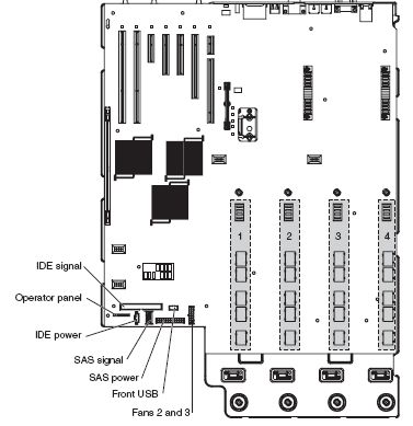
The following illustration shows the internal connectors on the I/O board:
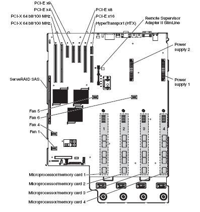
The following illustration shows the internal connectors on the I/O board for user-installable optional devices:
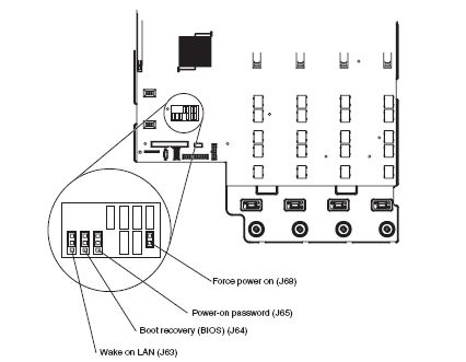
The following illustration shows the jumpers on the I/O board:
| Jumper | Settings |
|---|---|
| Force power on (J68) | Position a jumper over pins 1 and 2 on this two-pin jumper block to force the server to start up when you connect the server to ac power. |
| Power-on password (J65) | The default position is pins 1 and 2. Change the position of this jumper to pins 2 and 3 to bypass the power-on password check. Changing the position of this jumper does not affect the administrator password check if an administrator password is set. If you forget the administrator password, you must replace the I/O board. |
| Boot recovery (BIOS) (J64) | The default position is pins 1 and 2 (use the primary page during startup). Move the jumper to pins 2 and 3 to use the secondary page during startup. |
| Wake on LAN bypass (J63) | The default position is pins 1 and 2. Move the jumper to pins 2 and 3 to prevent a Wake on LAN packet from waking the system when the system is in the powered-off state. |
| Back to top |
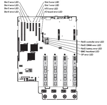
The following illustration shows the LEDs on the I/O board:
| Back to top |
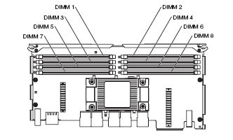
The following illustration shows the connectors on the microprocessor / memory card:
| Back to top |
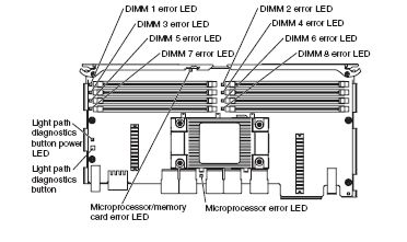
The following illustration shows the LEDs on the microprocessor/memory card:
| Back to top |
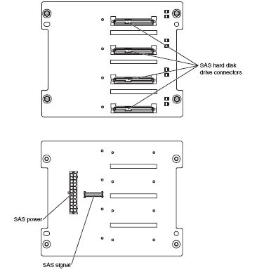
The following illustration shows the connectors on the SAS backplane:
| Problem Determination and Service Guide - IBM System x3755 (Type 8877) |
Document Location
Worldwide
[{"Type":"HW","Business Unit":{"code":"BU016","label":"Multiple Vendor Support"},"Product":{"code":"QUOEOZM","label":"System x->System x3755->8877"},"Platform":[{"code":"PF025","label":"Platform Independent"}],"Line of Business":{"code":"","label":""}}]
Was this topic helpful?
Document Information
Modified date:
24 January 2019
UID
ibm1MIGR-5070391