Product Documentation
Abstract
This document contains diagrams of the different system boards that comprise the IBM eServer xSeries 440.
Content
The IBM eServer xSeries 440 is comprised of several different system boards:
The following illustrations identify the connectors and LEDs on the centerplane board. The centerplane is used to connect the power and signal paths for each of the two SMP Expansion Modules, the I/O board, and the Remote Supervisor Adapter.

The following illustration identifies the internal connectors on the SMP Expansion Module board. This board enables you to install memory DIMMs and processors into the server. The system has two of these boards.
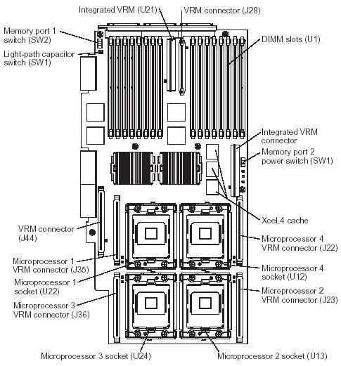
SMP Expansion Module LEDs diagram

The following illustration identifies the internal connectors on the PCI-X board. This board enables you to install adapters into the server.

The following illustration identifies the internal connectors on the I/O board. This board supports the input and output ports located on the server. This includes the SCSI, fan, power/reset, media bays, USB cable, and riser card connectors.
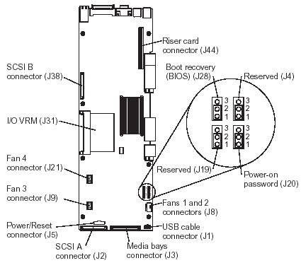
Note: The default position for J4, J10, J20 and J28 is pins 1 and 2.
| Power switch bypass |
|---|
The power switch can by bypassed (force power on) using the J5 connector on the I/O board.
- Unplug the J5 connector
- Either connect another power switch or connect pin 6 to pin 4 to simulate a button press

The following illustration identifies the connectors and lights on the Remote Supervisor Adapter.

| Additional information |
|---|
- IBM eServer xSeries 440 - System service part number listing
- IBM eServer xSeries 440 - Hardware Maintenance Manual
Document Location
Worldwide
Was this topic helpful?
Document Information
Modified date:
24 January 2019
UID
ibm1MIGR-52145