White Papers
Abstract
Preface:
The product name Db2 Analytics Accelerator for z/OS further on is referred to as "the Accelerator" (using the capital "A" as initial character). When talking about setup and functions, we talk about the "accelerator" (with a lower case "a" as initial character) regardless whether the setup is achieved by a single SSC LPAR (single-node) or by a cluster of SSC LPARs (multi-node).
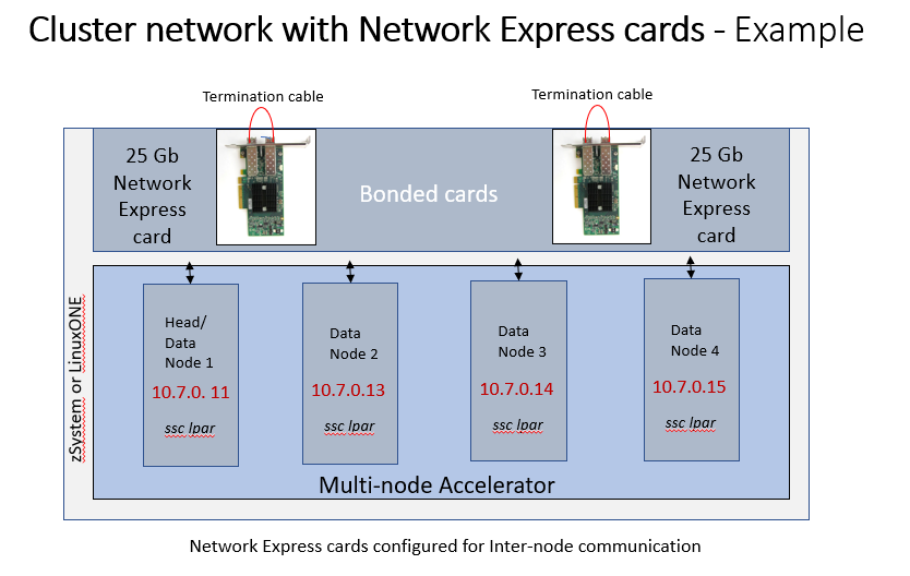
An Accelerator on Z multi-node installation includes the setup of a cluster network for inter-node communication.
Starting with Accelerator V8.1, the cluster network must use the RoCE communication.
The RoCE communication requires
- the Network Express interface when using IBM z17 or IBM LinuxONE Emperor 5 hardware
- the PCI adapter with a RoCE card when using IBM z16, z15, z14 or IBM LinuxONE Emperor 4, III, or II hardware.
With maintenance levels of Accelerator V7.5 prior to 7.5.10, HiperSockets have been used for inter-node communication in a cluster network. When migrating to Accelerator V8.1, it is required to change a HiperSockets-based cluster network to RoCE communication.
The RoCE communication provides the following benefits compared with HiperSockets:
- It consumes significantly less CPU resources than HiperSockets; thus, more of the power of the configured IFLs is used for workload execution.
- It increases the available CPU capacity for workload execution by ~10% compared with HiperSockets.
- It enhances the operational system stability in high workload situations.
This document describes how to
- configure the cluster network of a multi-node installation for RoCE communication using the Network Express interface.
- migrate a cluster network configuration using HiperSockets to one using the RocE communication.
For the configuration of a cluster network with RoCE cards instead of Network Express cards refer to technote https://www.ibm.com/support/pages/node/7031391
Content
- name: The name of the network interface definition. It must be the same for all LPARs, for example "roce".
- ipv4: The IP address of the network interface of this LPAR. The IP address must be different for each LPAR. The IP addresses of all LPARs of a multi-node cluster must all be in the same subnet.
- mode: The bonding mode. Use "balance-rr".
- FID: The function ID of a Network Express card port for the LPAR. Each Network Express card has two ports, and each port has its own FID. The function IDs per Network Express card and port are different for each LPAR.
{
    "version": "8.1.0",
    "accelerator_name": "IDAAONZ",
    "accelerator_description": "Accelerator with Network Express cards cluster network",
    "accelerator_type": "multi-node",
    "db2_pairing_ipv4": "10.20.92.119/24",
    "network_interface_bindings": {
        "mgmt_nw": "activation-profile",
        "db2_nw": "db2",
        "cluster_nw": "roce"
    },
    "runtime_environments": [
        {
            "cpc_name": "A100",
            "head": {
                "lpar_name": "LP01",
                "network_interfaces": [
                    {
                        "name": "db2",
                        ...
                    },
                    {
                        "name": "roce",
                        "ipv4": "192.168.101.229/24",
                        "bond_settings": {
                            "mode": "balance-rr",
                            "slaves": [
                                {
                                   "FID": "0000"
                                },
                                {
                                   "FID": "0001"
                                },
                                {
                                   "FID": "0002"
                                },
                                {
                                   "FID": "0003"
                                }
                            ]
                        }
                    }
                ],
                ....
            },
            ....
         }
       ...
}- Do not remove the HiperSockets interface definition so that the "network_interface_bindings" section initially continues to refer to the HiperSockets cluster network.
- Add the network interface definitions for the Network Express cards to each node in the "runtime_environments" section as a currently unused network.
{
    "version": "8.1.0",
    "accelerator_name": "IDAAONZ",
    "accelerator_description": "Accelerator with Network Express cards cluster network",
    "accelerator_type": "multi-node",
    "db2_pairing_ipv4": "10.20.92.119/24",
    "network_interface_bindings": {
        "mgmt_nw": "activation-profile",
        "db2_nw": "db2",
        "cluster_nw": "cluster"
    },
    "runtime_environments": [
        {
            "cpc_name": "A100",
            "head": {
                "lpar_name": "LP01",
                "network_interfaces": [
                    {
                        "name": "db2",
                        ...
                    },
                    {
                        "name": "cluster",
                        "ipv4": "192.168.100.229/24",
                        "device": "0.0.0008"
                    },
                    {
                        "name": "roce",
                        "ipv4": "192.168.101.229/24",
                        "bond_settings": {
                            "mode": "balance-rr",
                            "slaves": [
                                {
                                   "FID": "0000"
                                },
                                {
                                   "FID": "0001"
                                },
                                {
                                   "FID": "0002"
                                },
                                {
                                   "FID": "0003"
                                }
                            ]
                        }
                    }
                ],
                ....
            },
            ....
         }
       ...
}

- In the Admin UI, open the Diagnosis panel and select the Test your network tab.
- Starting from the head node, run ping commands to check the Network Express card cluster network IP address of each data node.
- Continue with data1 node. Run a ping command to check the head node and the remaining data nodes by using the cluster network IP address of each node.
- Continue with the remaining data nodes until you have pinged each node from each node on the cluster network IP address.
- Edit the JSON configuration file again and change the "network_interface bindings" from "cluster_nw":"cluster" to "cluster_nw":"roce". Note that "cluster" and "roce" are just sample names specified above in Step 2 of the JSON snippet examples. You can use different names in your JSON configuration file.
- Upload and apply the changed JSON configuration file using the Admin UI.
- Perform a Reset of the accelerator (do not select the wipe check box!) in the Admin UI to apply the new Network Express card cluster network across all accelerator nodes. This step incurs a short accelerator outage until all services have been started again. If the reset fails, perform a Shutdown on the Admin UI, followed by a re-activation of all accelerator LPARs to initiate a new restart.
                    {
                        "name": "cluster",
                        "ipv4": "192.168.100.229/24",
                        "device": "0.0.0008"
},Was this topic helpful?
Document Information
Modified date:
16 April 2026
UID
ibm17269546