Learn about how you can integrate IBM® Integration Bus into your HTTP topology, and
the consequences of different configurations for load-balancing, failover,
and administration.
The configuration of IBM Integration Bus in
each scenario described in this topic is closely connected to your
choice of HTTP listener. You can choose between integration node listeners
and integration server (embedded) listeners. To understand the differences
between these listeners, how to configure them, and how ports are
allocated to them, see HTTP listeners.
Learn about common HTTP topologies, and how to configure IBM Integration Bus in each case. Understand the
implications of your choice of topology and integration node configuration.
The following scenarios are listed in order of increasing complexity.
Scenario 1
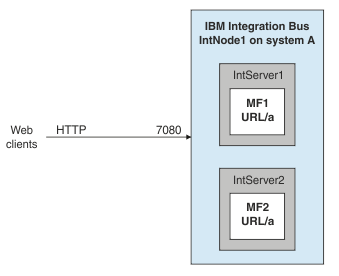
This scenario uses a single machine
and a single integration node. Ease of use is the highest priority;
load-balancing is relatively important; machine failover and high
throughput are not high priorities: This
scenario uses an integration node listener, listening on port 7080,
and all HTTP communication from the clients is processed by that listener.
Load-balancing is achieved by having additional instances of message
flows within integration servers, and by using the same URL in message
flows across integration servers.
Table 1. Strengths
and weaknesses of scenario 1:
| Strengths |
Weaknesses |
- Simplicity of administration and web service discovery: all inbound
requests (and any responses) are routed through a single port for
HTTP (and a second for HTTPS, if required).
- Load-balancing across message flows and integration servers: a
request to a specific web service (URL) can be processed by any message
flow registered to handle that URL. The message flows (MF1, MF2)
can be in separate integration servers (IntServer1, IntServer2),
and the requests are load balanced between them. As usual, within
each integration server you can deploy additional instances of each
flow, as required. This configuration offers a scalable load-balanced
solution with some degree of failover; if one integration server fails,
the others continue to process the workload while the first integration
server restarts.
|
- Failover: there is a single point of failure (integration node
or machine). If machine failover is implemented, it is complicated:
the secondary machine must take over the IP address of the primary
machine.
- Activity partitioning: there is no partitioning between activities
managed by the integration node.
- Throughput: a single listener handles all HTTP and all HTTPS messages
sent through two ports on the integration node. This single point
of processing and error handling can cause bottlenecks if high message
throughput is required.
|
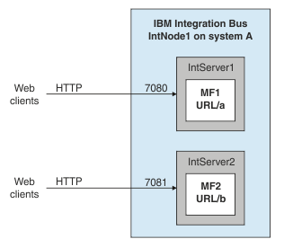
Scenario 2
This scenario uses a single machine
and a single integration node. High throughput is the highest priority;
machine failover and load-balancing are not high priorities:This scenario uses integration server listeners to improve
message throughput.
Table 2. Strengths and
weaknesses of scenario 2:
| Strengths |
Weaknesses |
- High throughput: you can deploy message flows to different integration
servers so that the HTTP (or HTTPS) messages can be handled by multiple
listeners on multiple ports to meet high throughput requirements
- Simple configuration: these listeners communicate directly with
the HTTP transport network; no intermediate queues are required
- Activity partitioning: activities managed by the integration node
are partitioned into separate integration servers
|
- Failover: there is a single point of failure (integration server,
integration node, or machine). If machine failover is implemented,
it is complicated, and involves the secondary machine taking over
the IP address of the primary machine
- You must include both the input and the reply nodes in the same
message flow, or deploy separate message flows to the same integration
server, so that they use the same listener; matching input and reply
messages must be processed by the same port
|
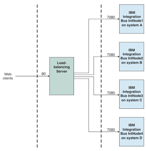
Scenario 3
This scenario uses multiple machines
and multiple integration nodes. Failover is the highest priority;
load-balancing and security are also important:This scenario uses integration
node listeners. There is also a server that acts as a load balancer
and a network dispatcher, thus simplifying the client interface. The
configuration of message flows and integration servers is replicated
across multiple integration nodes, and the load-balancing server is
configured to manage high availability cluster multiprocessing (HACMP) across the integration nodes.
Table 3. Strengths and weaknesses of scenario 3:
| Strengths |
Weaknesses |
- Load balancing: having a server that acts as a network dispatcher
and load balancer provides additional load-balancing capability to
this scenario
- Failover: the distribution of integration nodes across systems
allows for both machine and integration node failover
- Simplified client configuration: the load-balancing server provides
a single point of contact for clients
|
- Complexity: the scenario is complex, although the complexity can
be hidden from clients and managed in centralized locations
|