Network topology
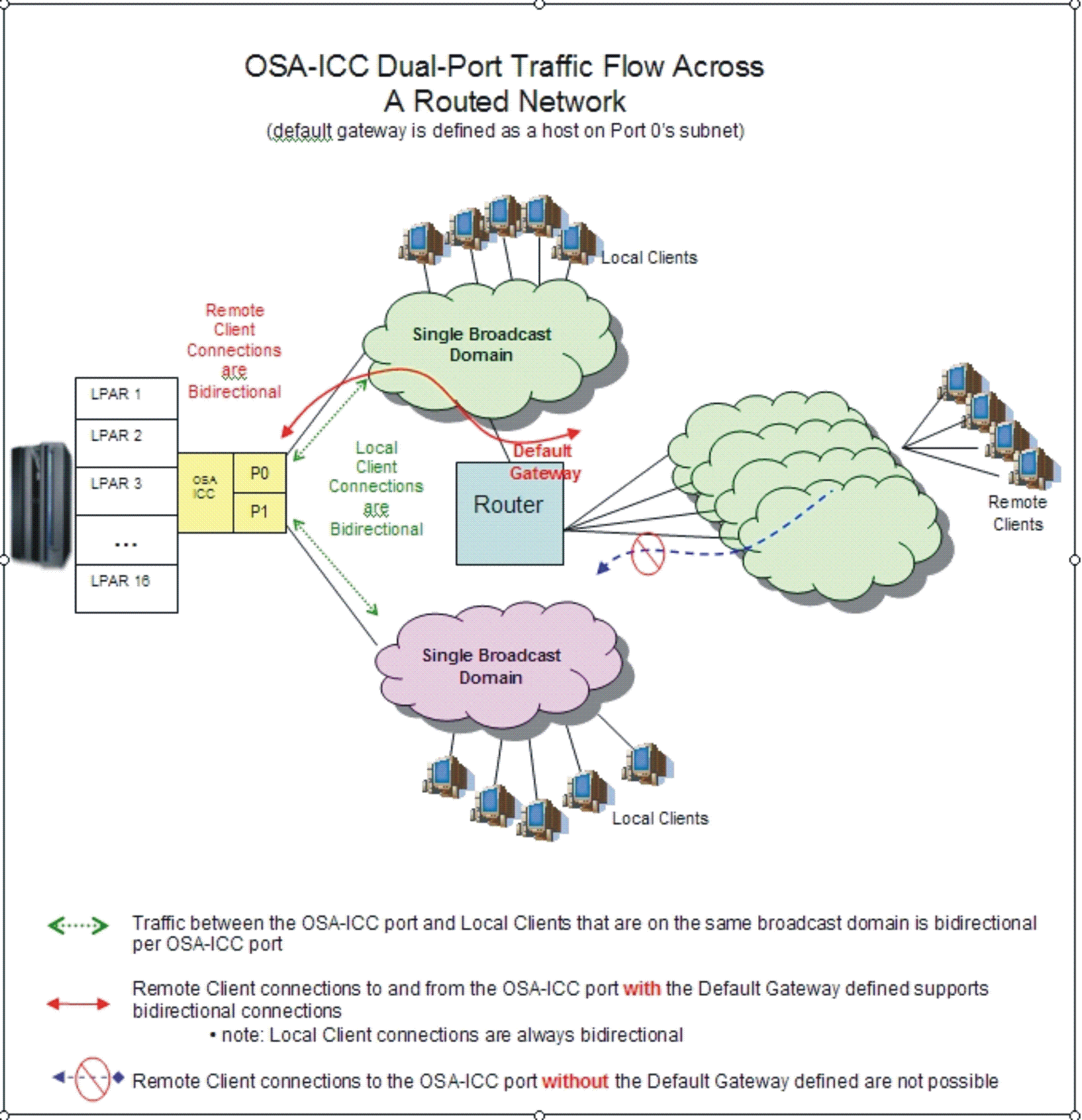
The OSA-ICC adapter supports two physical ports for each pchid. The server definition for each physical port defines a unique secure and/or non-secure TCP port number, IP address and subnet. These server definitions allow for an isolated Local Area Network (LAN) to be created for each physical port. Any external network traffic is routed through a common default gateway defined for both ports. An example illustrating an OSA-ICC multi-port connection is given in the network topology diagram in Figure 1.

Figure 1 shows connectivity to an ICC adapter where each physical port (P0, P1) is configured on a different broadcast domain (LAN). Both P0 and P1 clients communicate with OSA through the defined TCP port. The external network traffic is only allowed to travel in one direction through P0 because the local clients reside on the same subnet as the default gateway. The clients connected to P1 are restricted to communicate only with the clients of that subnet.