- Basic sampling
- Diagnostic sampling
 The HIS Profiler
  returns sampling data entries
in a z/OS UNIX System Services
output file (SYSHISyyyymmdd.hhmmss.xxx.SMP.cpu#)
in the HOME directory or the user-specified directory. The .SMP files
are not printable.
If collecting .SMP files, large amounts of space might be needed in the file system containing the .SMP files. You might need to specify the disk space needed for the file system that the sampling data is written in when you set up a hardware event data collection. Sampling buffers are 4KB in size. The last 64 bytes of each buffer are reserved for system use. A basic sample is 32 bytes in length. A diagnostic sample is 64 bytes in length. The required disk space depends on the amount of samples that need to be captured.
For basic sampling, the number of samples that fit in each 4KB buffer is (4096-64)/32 = 126. If only the basic sampling is requested, the disk space can be calculated by the formula: (Number of basic samples / 126) * 4K.
If diagnostic sampling is requested, basic sampling is also automatically included. Hence a combined basic and diagnostic sampling takes three times as much disk space as basic sampling alone.
- Basic sampling entry
- The basic sampling function is the standard part of the CPU-measurement
sampling facility and is the default sampling function type. If the
system performs basic sampling function, HIS returns the basic sampling
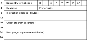
entry data in a .SMP output file. The following figure shows the data
structure of a basic sampling entry. Figure 1. Data structure of a basic sampling entryIn the basic sampling data entry:

- Data entry format code
- Bits 0–15 of the data entry contains the format code of the data entry.
- Reserved (R)
- Bits 16-19 of the data entry are reserved for programming use. Zeros are stored in this field.
- Number of unique instructions (U)
- Bits 20-23 of the data entry specify the number of unique, completed instructions that were executed simultaneously during the sampling cycle when the unique cycle indicator is on.
- DAT mode (T)
- Bit 26 of the data entry contains the DAT mode bit in the PSW of the CPU.
- Wait state (W)
- Bit 27 of the data entry contains the wait state bit in the PSW of the CPU.
- Problem state (P)
- Bit 28 of the data entry contains the problem state bit in the PSW of the CPU.
- Address-space control (AS)
- Bits 29-30 of the data entry contain the address-space control in the PSW of the CPU.
- Invalid indication (I)
- Bit 31 of the data entry indicates whether the entry is valid or not. When the bit is zero, the entry is valid; when the bit is one, the entry is not valid. An entry is set to not valid when sample data in the entry is not consistent.
- Reserved
- Byte offsets 4-5 of the data entry are reserved. Zeros are stored in this field.
- Primary ASN
- Byte offsets 6-7 of the data entry contains the primary ASN in bits 48-63 of control register
- Instruction address
- Byte offsets 8-15 of the data entry contains the instruction address of an instruction that the logical processor was executing during the sampling cycle.
- Guest program parameter
- Byte offsets 16-23 of the data entry contains the program parameter
set by the most recent SET PROGRAM PARAMETER instruction executed
by the processor running at the virtual- machine level.
Note that the program parameter of z/OS® is always stored in the guest program parameter field.
- Host program parameter
- Byte offsets 24-31 of the data entry contains the program parameter set by the most recent SET PROGRAM PARAMETER instruction executed by the processor running under VM.
The z/OS dispatcher stores the 8–byte guest program parameter instruction at each dispatch to identify the currently executing address space or task to the hardware. This program parameter with the address space or task ID is included in the basic sampling output.Note: The z/OS system only uses the guest program parameter. The key fields in the guest program parameter are: Wait (W), SRB mode (S), TCB address, WEB address, and HOME ASN. The Task ID token and Partial WEB Address fields provide additional information for identifying the dispatched work units (task or SRB).If running under a TCB , the data structure of the guest program parameter is shown as follows:Figure 2. Data structure of a guest program parameter under a TCB If running under an SRB, the data structure of the guest program parameter is shown as follows:Figure 3. Data structure of a guest program parameter under an SRB
 In the structure of a guest program parameter:
- W (1 bit)
- Wait is dispatched. The processor is going into a waiting state.
- TCB address (24 bits)
- The address of the TCB for which the instruction address is being recorded in the sample entry.
- S (1 bit)
- SRB mode. If the value of S is one, the work is processed in SRB mode. This bit is always zero when running in task mode.
- Home ASN (15 bits)
- The HOME ASID of the task or SRB for which the instruction address is being sampled.
- Task ID token (16 bits)
- The Task ID token provides additional identify information on the task to differentiate it from other tasks within the same ASID.
- WEB address (32 bits)
- WEB address of the SRB for which the instruction address is being recorded in the sample entry.
- Partial WEB address (16 bits)
- Partial WEB address provides additional identify information on the SRB to better differentiate it from other SRBs within the same ASID.
- Diagnostic sampling entry
- The diagnostic sampling function is optional. The diagnostic
sampling function provides details of the internal hardware design.
If you want to use the diagnostic sampling function, you must first
authorize to the diagnostic sampling function on the SE console.
When diagnostic sampling is requested, basic sampling is also automatically
selected. A basic sampling entry is automatically written ahead of
each diagnostic sampling entry.
 The HIS Profiler
  returns
both the basic sampling entry data and the diagnostic sampling entry
data in a .SMP output file. The data format of a diagnostic sampling
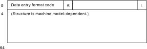
entry varies on different models. The following figure shows the general
data structure of a diagnostic sampling entry. In the diagnostic sampling entry:Figure 4. Data structure of a diagnostic sampling entry
- Data entry format code
- Bits 0–15 of the data entry contains the format code of the data entry.
- Reserved (R)
- Bits 16-19 of the data entry are reserved for programming use. Zeros are stored in this field.
- Invalid indication (I)
- Bit 31 of the data entry indicates whether the entry is valid or not valid. When the bit is zero, the entry is valid; when the bit is one, the entry is not valid. An entry is set to not valid when sample data in the entry is not consistent.
- Structure
- Byte offsets 4-64 of the data entry contains the various structures for the diagnostic sampling entries on different models.