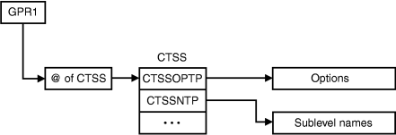
Component trace passes information to the display exit routine in a parameter list and in General Purpose Registers (GPRs).
Registers at entry: On entry to the display routine, the GPRs and access registers (ARs) contain the following information:
| Register | Contents |
|---|---|
| GPR 0 | No applicable information |
| GPR 1 | Address of a standard parameter list, which contains the address of the component trace parameter list (CTSS). |
| GPRs 2 - 12 | If you use these registers, you must save and restore the contents. |
| GPR 13 | Address of a 72-byte register save area, located in pageable, private-area storage. |
| GPR 14 | Return address. |
| GPR 15 | Entry point address of the display routine. |
| ARs 0 - 15 | If you use these registers, you must save and restore the contents. |
- A table containing the options from an operator REPLY or parmlib member (CTSSOPTP)
- A sublevel table (CTSSSNTP) if sublevels are involved in the request.

The CTSSUSRD field of CTSS contains the 16 bytes of information specified on the USERDATA parameter of CTRACE DEFINE. This field will contain zeros if not specified on CTRACE DEFINE. This CTSS user data is treated as input to and output from the display routine, and it can be changed by the display routine.
The standard parameter list, the CTSS, and OPTIONS buffer table are located in pageable, private-area storage. The CTSS is mapped by the ITTCTSS mapping macro. For the field descriptions provided by the ITTCTSS mapping macro, see CTSS in z/OS MVS Data Areas in the z/OS Internet library.