- The
application name (NAME parameter). The
operator uses this name on the TRACE CT command (COMP parameter).
When formatting trace data with IPCS, use this name on the IPCS CTRACE
subcommand (COMP parameter). The application name is required. Note: Do not use names that begin with the prefix SYS. The prefix SYS is reserved for use by IBM®.
- A parmlib member name (PARM parameter). Identifying a parmlib member establishes the initial tracing options for an application. These options can be overridden by operator commands. This parameter is optional. (See Using parmlib members for more information.)
- A head level (HEAD parameter) and a sublevel trace name (SUB parameter). These parameters are related to multiple traces. (See Using multiple traces for more information).
- The load module that contains the CTRACE format table (FMTTAB parameter), which controls trace formatting in the IPCS CTRACE subcommand.
- The name of the start/stop exit routine (STARTNAM parameter). The system gives this routine control when the operator enters a TRACE CT command or when you specify the PARM parameter on CTRACE DEFINE.
- The name of the display trace exit routine (DISPNAM parameter). The system gives this routine control when the operator enters a DISPLAY TRACE command.
- A list of default, user-defined tracing options (MINOPS parameter). If you specify MINOPS, tracing with these options will be in effect at all times and cannot be turned off.
- An indication that the application supports an external writer (WTR and WTRMODE parameters).
Specifying parmlib on CTRACE DEFINE: When you specify a parmlib member on CTRACE DEFINE, the system uses the tracing options specified in that parmlib member. If that parmlib member contains instructions to turn the trace on, then the system passes control to the application's start/stop exit routine without operator intervention. If you update the parmlib member, you change the tracing options used when the application subsequently issues CTRACE DEFINE with that same parmlib member.
CTRACE DEFINE,NAME=ABC,PARM=CTXABC01...TRACEOPTS
ON
ASID(01)
OPTIONS('original options')TRACE CT,ON,COMP=ABC
REPLY xx,ASID=(01),OPTIONS=('original options'),ENDA parmlib member you specify on CTRACE DEFINE can contain information about only a single trace. If you are defining multiple traces, include in each parmlib member options that pertain only to the specific head level or sublevel trace. The following topic explains head level and sublevel traces.

- HEADOPTS=YES on CTRACE DEFINE when you create the head level
- LIKEHEAD=YES on CTRACE DEFINE when you create the sublevel traces.
- Independent traces with unique tracing features (LIKEHEAD=NO on CTRACE DEFINE)
- Traces that use a head level's attributes, options and mode (LIKEHEAD=YES on CTRACE DEFINE).
Figure 2 lists the characteristics, options, and status associated with a trace. If an application defines a sublevel trace to match its head level, LIKEHEAD, any changes to the head level options and status are reflected in the sublevel trace.
- ASIDS=YES/NO
- JOBS=YES/NO
- MINOPS
- MOD=YES/NO
- BUFFER=YES/NO
- BUFMIN
- BUFMAX
- BUFDFLT
- BUFDEFIN=YES/NO
- WTR=YES/NO
- STARTNAM
- FMTTAB
- HEAD=YES/NO
- LIKEHEAD=YES/NO
- MANYSUBS=YES/NO
- ASID
- JOBNAME
- OPTIONS
- BUFSIZE
- WTR
- ON
- OFF

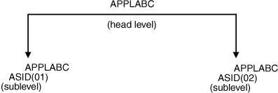
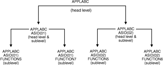
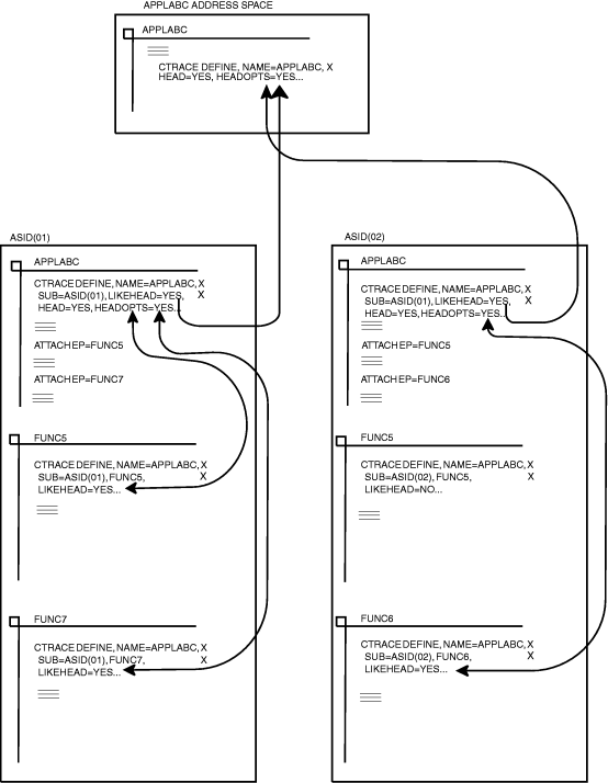
- During initialization, APPLABC issues CTRACE DEFINE and specifies APPLABC as the head level (by specifying HEAD=YES and NAME=APPLABC on CTRACE DEFINE). APPLABC also specifies HEADOPTS=YES to allow its sublevel traces to share its attributes, options, and status.
- The first time APPLABC gets control in address space ASID(01), APPLABC issues CTRACE DEFINE for sublevel ASID(01), with LIKEHEAD=YES and HEAD=YES. Now, ASID(01) is established as a sublevel trace with the same tracing attributes, options, and status as its head level, APPLABC, and ASID(01) is also established as a head level.
- APPLABC issues another CTRACE DEFINE for sublevel trace FUNCTION5, with LIKEHEAD=YES. Now FUNCTION5 is established as a sublevel trace, and uses all the attributes, options, and status from its head level, ASID(01), and ASID(01)'s head level, APPLABC.
- APPLABC defines FUNCTION7 in the same way as FUNCTION5.
- When APPLABC gets control in address space ASID(02), APPLABC issues CTRACE DEFINE to establish itself as a head level, and again to establish ASID(02) as a sublevel trace with the same parameters as ASID(01).
- APPLABC establishes FUNCTION5 and FUNCTION6 as sublevel traces. Even though FUNCTION5 is also in ASID(01), FUNCTION5 can have unique tracing features in ASID(02) by specifying LIKEHEAD=NO (or taking the default).

Using the component trace external writer: To define your application to component trace to support an external writer, issue CTRACE DEFINE with the WTR=YES and WTRMODE parameters. The WTR=YES parameter indicates the application supports having its trace buffers written to trace data sets on DASD or tape. The WTRMODE parameter specifies the type of storage your application is using for its trace buffers. The WTRMODE values are PAGEABLE, DREF, or FIXED.