 z/OS MVS Programming: Extended Addressability Guide
 z/OS MVS Programming: Extended Addressability Guide
|
Previous topic |
Next topic |
Contents |
Contact z/OS |
Library |
PDF
Linkage stack z/OS MVS Programming: Extended Addressability Guide SA23-1394-00 |
|
|
The linkage stack is an area of protected storage that the system gives a program to save status information at a branch or a program call. This section describes the linkage stack and the assembler instructions that cause the system to add and remove an entry and modify the entry. Saving status is a required part of program linkage. Status includes general purpose registers (GPRs), access registers (ARs), the PSW, and other important information. The first thing a program does when it receives control is save the status of its caller. The last thing the program does before it returns control is restore the caller's status. The calling program can then resume processing with its status (including registers and cross memory environment) intact. For example, your PC routines might have used the PCLINK STACK macro to save a caller's status and then the PCLINK UNSTACK macro to restore the status. An easier way to save and restore status, however, is to allow
the system to do it for you through the linkage stack. The linkage stack saves you and
the system work in the following ways:
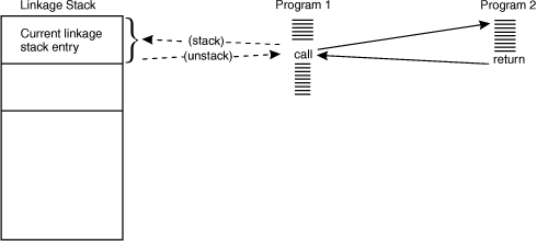
The following illustration shows how a program uses the linkage stack. The call from Program 1 to Program 2 automatically places all the caller's status on the linkage stack. The return from Program 2 to Program 1 automatically restores all the caller's status and removes the entry from the linkage stack.  The system provides each workunit (that is, TCB or SRB) with its own linkage stack. The linkage stack is then available to all programs that the workunit represents. The programs can run in primary or AR address space control (ASC) mode. They can be problem state or supervisor state, locked or unlocked, enabled or disabled. The linkage stack actually consists of two stacks: the normal linkage stack and the recovery linkage stack. The normal linkage stack consists of at least 96 entries (for tasks) or 57 entries (for SRBs) for use by programs that run under the workunit. (Note that under some circumstances, the system might provide more than this.) When the system needs an entry and finds that all entries in the normal stack are used, it abends the program with a "stack full" interruption code. After the "stack full" interruption occurs, the system uses the recovery linkage stack. The recovery linkage stack is available to the program's recovery routines after the "stack full" interruption occurs. If you anticipate a need for more than 96 entries, you can use the LSEXPAND macro to expand the size of the normal and recovery stacks for tasks. For information about how and when to issue the LSEXPAND macro, see Expanding a linkage stack to a specified size. 


|
 Copyright IBM Corporation 1990, 2014 Copyright IBM Corporation 1990, 2014 |