Switch configuration on a RoCE network (Linux)
Switch failover capability is a high availability feature provided by the configure Link Aggregate Control Protocol (LACP) on the switch.
Before you begin
The configuration procedure for switch failover detailed in this topic applies to both SuSE Linux® Enterprise Server (SLES) systems and Red Hat Enterprise Linux Server (RHEL) systems on a remote direct memory access (RDMA) over Converged Ethernet (RoCE) network.
This procedure does not apply to IBM® BladeCenter environments. To configure switch failover support for BladeCenter deployments, no actions are performed on the switch modules, but you must configure multiple cluster interconnects on the primary and secondary cluster caching facilities (CFs) and members.
- Set up your network topology according to one of the supported network topologies listed in Network topology configuration support for Db2 pureScale environments.
- Power on the switch and connect an RJ11 serial cable or Ethernet cable to the switch.
Administrative access is required on the switches.
About this task
- Link Aggregate Control Protocol (LACP) for switch failover configuration
- Global Pause flow control (IEEE 802.3x)
- Optional. Support of local loopback IP address on the switch that can be pinged by IP addresses on the same IP subnet. For more details and restrictions on this, refer to the technote on Restrictions of automated adapter liveliness test.
This procedure configures multiple switches to support switch failover. Switch failover capability helps the resiliency or fault tolerance of a network. These steps are not applicable for a single switch setup.
To create a Db2 pureScale environment with multiple switches, you must have multiple cluster interconnects on CF and member servers and configure switch failover on the switches.
Procedure
-
Repeat the above on all switches in the cluster.
Figure 1. Two CFs and four members connect to two switches. 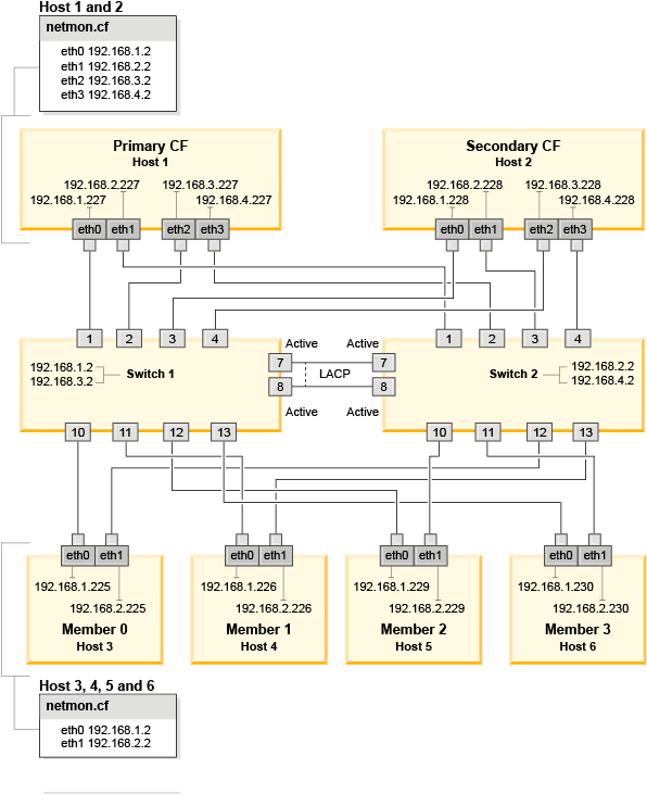
What to do next
Configure the network settings of hosts that you plan to include in the Db2 pureScale environment.