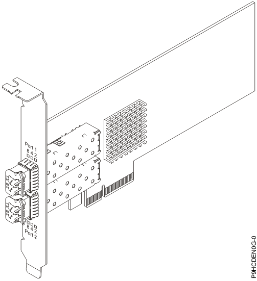
PCIe2 8 Gb 2-port Fibre Channel adapter (FC EL5Y, FC EL5Z, FC EN0F, and FC EN0G; CCIN 578D)
Learn about the specifications and operating system requirements for feature codes (FC) EL5Y, FC EL5Z, FC EN0F, and FC EN0G adapters.
Overview
FC EL5Y and FC EN0F is a low-profile adapter and FC EL5Z and FC EN0G is a full-height adapter.
The PCIe2 8 Gb 2-port Fibre Channel adapter is a PCI Express (PCIe) generation 2 (Gen2), high-performance, x8 short form factor pluggable plus (SFP+) Host Bus. This adapter enables multiple logical (virtual) connections to share the same physical port. Each logical connection has its own resources and the ability to be managed independently. Each port provides single initiator capability over a fiber link or provides multiple initiator capability with N_Port ID Virtualization (NPIV). The ports are connected by using LC type connectors. These connectors use shortwave laser optics. The adapter operates at link speeds of 2, 4, and 8 gigabits per second (Gbps) and automatically negotiates to the highest speed possible. LEDs on each port provide information about the connection status and link speed of the port. The adapter connects to a Fibre Channel switch.

Specifications
- Item
- Description
- Adapter FRU number
- 00WT111
- I/O bus architecture
- PCIe2.0 x8
- Slot requirement
- For details about slot priorities, maximums, and placement rules, see PCIe adapter placement rules and slot priorities and select the system you are working on.
- FC compatibility
- 2, 4, 8 Gigabit
- Cables
- Cables are the responsibility of the customer. Use multimode fiber optic cables with shortwave lasers that adhere to the following specifications:
- OM3: Multimode 50/125 micron fiber, 2000 MHz x km bandwidth
- OM2: Multimode 50/125 micron fiber, 500 MHz x km bandwidth
- OM1: Multimode 62.5/125 micron fiber, 200 MHz x km bandwidth
Table 1. Supported distances for multimode fiber optic cables Header Cable Type and Distance Rate OM1 OM2 OM3 2.125 Gbps 0.5 meters to 150 meters (1.64 feet to 492.12 feet) 0.5 meters to 300 meters (1.64 feet to 984.25 feet) 0.5 meters to 500 meters (1.64 feet to 1640.41 feet) 4.25 Gbps 0.5 meters to 70 meters (1.64 feet to 229.65 feet) 0.5 meters to 150 meters (1.64 feet to 492.12 feet) 0.5 meters to 380 meters (1.64 feet to 1246.71 feet) 8.5 Gbps 0.5 meters to 21 meters (1.64 feet to 68.89 feet) 0.5 meters to 50 meters (1.64 feet to 164.04 feet) 0.5 meters to 150 meters (1.64 feet to 492.12 feet) - Voltage
- 12 V
- Form factor
- Short, low-profile (FC EL5Y and FC EN0F)
- Maximum number
- For details about the maximum number of adapters that are supported, see Adapter placement rules and slot priorities and select the system you are working on.
- Attributes provided
- NPIV capability is supported through VIOS
Operating system or partition requirements
- The latest version of enabling libraries and utilities can be downloaded from the Fix Central website.
- Power Systems Prerequisites website.
- IBM System Storage Interoperation Center (SSIC) website.
- The latest version of the device driver or IBM® Power® RAID adapter utilities (iprutils) can be downloaded from the IBM Service and Productivity Tools website.
- For information about important notices for Linux on IBM Power Systems, see the Linux® on IBM website.
Adapter LED
| Hardware State | Yellow LED (8 Gbps) | Green LED (4 Gbps) | Amber LED (2 Gbps) | Comments |
|---|---|---|---|---|
| Power Off | Off | Off | Off | |
| Power On (before firmware initialization) | On | On | On | |
| Power On (after firmware initialization) | Flash | Flash | Flash | All flash at the same time. |
| Firmware Fault | Flash in sequence | Flash in sequence | Flash in sequence | Flashing in sequence of yellow LED, green LED, amber LED, then back to yellow LED. |
| 2 Gbps Link UP/ACT | Off | Off | On/Flash | On for link up and flash if I/O activity. |
| 4 Gbps Link UP/ACT | Off | On/Flash | Off | On for link up and flash if I/O activity. |
| 8 Gbps Link UP/ACT | On/Flash | Off | Off | On for link up and flash if I/O activity. |
| Beacon | Flash | Off | Flash | All flashing at the same time. |