If you have a SCSI disk enclosure attached to the system you might
want to disconnect the SCSI cable at the enclosure to prevent a potential
SCSI address conflict on the attached enclosure when you power down the system.
Disconnect the power source from the system by unplugging the system.
Note: This system is equipped with a second power supply. Before continuing
with this procedure, ensure that all power sources to the system have been
completely disconnected.
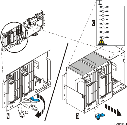
Locate the blue handle, which is below the processor assembly.
Attention: The system backplane assembly is of substantial
weight and should not be pulled out using the blue lever. Grasp the system
backplane assembly firmly with both hands when it is free of the system.
As shown in the following figure, push the blue lever A to
the left and out from the system to unlock the system backplane assembly,
and then pull the system backplane assembly B out of
the system using both hands.
Figure 1. Slide the model 9116-561 or570 system
backplane assembly out of the system unit
If you are removing the system backplane as a part of another procedure,
return to that procedure. If you are removing the system backplane
because it is damaged or failing to operate correctly, continue to the next
step.
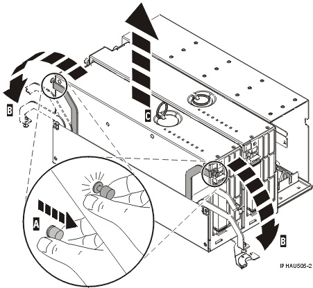
As shown in the following figure, pull out on the locking knobs A until
you feel them unlock. Push the locking arms B down
and out to unlock the processor assembly, and then lift it out of the system
backplane assembly C. Remove all processor assemblies
(or fillers) from the system backplane assembly.
Tip: Record the
location of each processor assembly being removed for use during reinstallation.
Figure 2. Remove the processor assembly from model 9116-561 or570 backplane
assembly
Place the processor assembly on a surface that is safe from electrostatic
discharge.