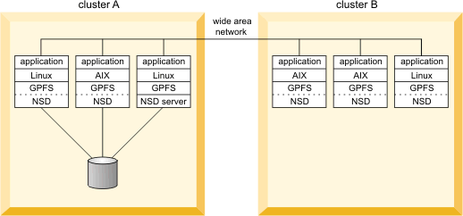
Accessing a remote GPFS file system

GPFS™ allows users shared access to files in either the cluster where the file system was created, or other GPFS clusters. File system access by the cluster where the file system was created is implicit.

The ability to access and mount GPFS file systems owned by other clusters in a network of sufficient bandwidth is accomplished using the mmauth, mmremotecluster and mmremotefs commands. Each site in the network is managed as a separate cluster, while allowing shared file system access.

The cluster owning the file system is responsible for administering the file system and granting access to other clusters on a per cluster basis. After access to a particular file system has been granted to nodes in another GPFS cluster, the nodes can mount the file system and perform data operations as if the file system were locally owned.

Each node in the GPFS cluster requiring access to another cluster's file system must be able to open a TCP/IP connection to every node in the other cluster.

Nodes in two separate remote clusters mounting the same file system are not required to be able to open a TCP/IP connection to each other. For example, if a node in clusterA mounts a file system from clusterB, and a node in clusterC desires to mount the same file system, nodes in clusterA and clusterC do not have to communicate with each other.

Each node in the GPFS cluster requiring file system access must have one of the following:
  • A virtual connection to the file system data through an NSD server (refer to Figure 1).
  • A physical connection to the disks containing file system data (refer to Figure 2).

In this example, network connectivity is required from the nodes in clusterB to all the nodes in clusterA even if the nodes in clusterB can access the disks in clusterA directly.

Figure 1. Remote mount of a file system using NSD server access
Remote mount of a file system using NSD server access. This graphic shows two GPFS clusters named cluster A and cluster B, and a wide area network connecting them. Cluster A consists of three nodes and one disk. One node runs AIX and the other two run Linux. All three nodes are connected to the disk. One of the Linux nodes is also the NSD server, and this node is connected to the wide area network. The other two nodes are not connected to the wide area network. Cluster B consists of three nodes, two of which run AIX and one of which runs Linux. All three nodes are connected to the wide area network. There are no disks in cluster B.
Figure 2. Remote mount of a file system using SAN-attached disks
Remote mount of a file system using SAN-attached disks. This graphic shows two GPFS clusters named cluster A and cluster B. Cluster A consists of three nodes and one disk. One node runs AIX and the other two run Linux. All three nodes are connected to the disk. Cluster B consists of three nodes, two of which run AIX and one runs Linux. All three nodes are connected to the disk associated with cluster A. Cluster B has no disks of its own.
Figure 3 illustrates a multi-cluster configuration with multiple NSD servers. In this configuration:
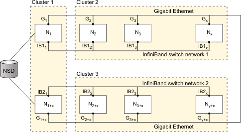
  • The two nodes in Cluster 1 are defined as the NSD servers (you can have up to eight NSD server nodes).
  • All three clusters are connected with Gigabit Ethernet.
  • Cluster 1 shares an InfiniBand switch network with Cluster 2 and an InfiniBand switch network with Cluster 3.
Note: Protocol support is not available in a multi-cluster configuration.
In order to take advantage of the fast networks and to use the nodes in Cluster 1 as NSD servers for Cluster 2 and Cluster 3, you must configure a subnet for each of the supported clusters. For example issuing the command:
  • mmchconfig subnets="<IB_Network_1> <IB_Network_1>/Cluster1" in Cluster 2 allows nodes N2 through Nx to use N1 as an NSD server with InfiniBand Network 1 providing the path to the data.
  • mmchconfig subnets="<IB_Network_2> <IB_Network_2>/Cluster1" in Cluster 3 allows nodes N2+x through Ny+x to use N1+x as an NSD server with InfiniBand Network 2 providing the path to the data.
Figure 3. Multi-cluster configuration with multiple NSD servers
Illustration shows three clusters with two of them being remote clusters. Cluster 1 contains the two NSD servers for this configuration. Cluster 2 and Cluster 3 use separate networks to access the NSD servers in Cluster 1. With this configuration, Cluster 2 and Cluster 3 can access the data stored on the NSDs without having a direct connection to those disks.