Steps for configuring the partner company with NAT model (host-to-host with IPSec)

In the partner company with NAT model, the partner company model topology is modified to include private addressing in the private network of each partner company, with a NAT device in front of each private network.

Before you begin

The following statements and concepts are covered in the discussion of this model:

  • AllowNat and NatKeepAliveInterval parameters on the KeyExchangePolicy and KeyExchangeAction statements
  • IKE traffic on UDP port 4500, in addition to port 500
  • NAT implications for host-to-host dynamic IKE negotiations:
    • Local and remote data endpoints
    • Local and remote security endpoints
    • IKE initiator and responder roles
    • Restriction on HowToAuth protocol (AH not supported)
  • Using wildcards for location and identity
  • RSA signature peer authentication
  • Certificates and certificate authorities
  • CaLabel
  • SupportedCertAuth

Steps for configuring the partner company model (host-to-host with IPSec) assumed a network topology with both partner companies using public IP addresses in their internal networks. Often one or both businesses have an internal network that uses IETF-defined private IP addresses (10.0.0.0/8, 172.16.0.0./12, and 192.168.0.0/16). Private IP addresses cannot be routed outside an internal network. Network address translation (NAT) is used to create a mapping of private addresses to public addresses and perform the necessary translation as packets traverse the NAT device.

When IPSec Security Associations traverse a NAT, there are problems because the NAT is unable to update IP addresses and checksums that are part of the encapsulated data (encrypted, authenticated, or both). The IETF has defined a solution known as NAT traversal (NATT) that allows IPSec Security Associations to successfully traverse a NAT device.

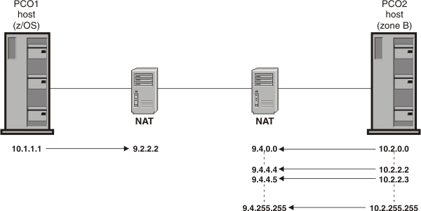
Figure 1 shows the partner company with NAT topology when the partner company model topology has been modified to include private addressing in each partner company's private network with a NAT device in front of each private network.

Figure 1. Partner company with NAT model
Shows PCO1 z/OS host connected to PCO2 host in untrusted zone B, with NAT in front of each company network.

The steps in this topic will describe the configuration considerations and requirements when the NATT solution is implemented to traverse NAT devices in a host-to-host environment. The partner company with NAT model has the same basic security requirements as the partner company model. Configuration statements added or changed for the partner company with NAT model are shown in bold. The example describes the policy for partner company 1 (PCO1).

For this example, assume you must meet the following requirements to allow network communications from a partner company (PCO2) in an untrusted zone B behind a NAT over a connected network (9.4.0.0/16) to a server on this host that is behind a NAT:

  • IKE traffic from untrusted zone B that is behind a NAT is allowed to this host that is behind a NAT.
  • Secure FTP traffic (using TLS/SSL) from untrusted zone B is allowed to a secure FTP server running on this host.
  • Enterprise Extender (EE) traffic from untrusted zone B is allowed to an EE service running on this host using a dynamic IPSec tunnel with strong encryption and authentication.
  • FTP traffic from untrusted zone B is allowed to an FTP server running on this host using a dynamic IPSec tunnel with strong authentication.
  • The dynamic IPSec tunnel for EE is activated when outbound EE traffic is detected (on-demand activation).
  • A dynamic IPSec tunnel for normal FTP control activates for each remote host that initiates an FTP connection (remote activation).
  • A dynamic IPSec tunnel for normal FTP data activates for each remote host that initiates an FTP data connection (remote activation).
  • Peers authenticate themselves using the RSA signature method.

Procedure

Perform the following steps to meet these requirements and configure the partner company with NAT model.

  1. For each zone, determine what services are allowed:
    • IKE traffic
    • Normal FTP traffic
    • Secure FTP traffic
    • Enterprise Extender traffic
  2. Define an IpService statement for each wanted service.
    • IKE traffic

      When NAT traversal is allowed, IKE uses UDP port 500 and port 4500 for message exchanges. NAT traversal is controlled by the AllowNat parameter on the KeyExchangePolicy and KeyExchangeAction statements.

      IpService                    IKE-local-500
      {
        SourcePortRange            500
        DestinationPortRange       500
        Protocol                   UDP
        Direction                  bidirectional
        Routing                    local
        SecurityClass              0
      }
      
      IpService                    IKE-local-4500
      {
        SourcePortRange            4500
        DestinationPortRange       4500
        Protocol                   UDP
        Direction                  bidirectional
        Routing                    local
        SecurityClass              0        		
      }
    • Normal FTP traffic

      When a NAT is being traversed, FTP clients typically need to use passive mode (PASV) or extended passive mode (EPSV) to connect to the FTP server, allowing inbound connections but not outbound connection requests. For more information on active and passive mode FTP, see Considerations for IPSec-encapsulated FTP traffic when traversing a NAT.

      Two services are required, one for the control connection and one for the data connection. The range of server ports specified for the data connection reflects the port range specified for PASSIVEDATAPORTS in the server's FTP.DATA file. For more information on PASSIVEDATAPORTS, see z/OS Communications Server: IP Configuration Reference.

      The following definitions show the services required for the FTP server for EPSV mode:

      IpService                    FTPServer-Control
      {
        SourcePortRange            21
        DestinationPortRange       1024 65535
        Protocol                   tcp
        Direction                  bidirectional InboundConnect
        Routing                    local
        SecurityClass              0
      }
      
      IpService                    FTPServer-Data-Passive
      {
        SourcePortRange            50000 50200  
        DestinationPortRange       1024 65535
        Protocol                   tcp
        Direction                  bidirectional InboundConnect
        Routing                    local
        SecurityClass              0
      }
    • Secure FTP traffic

      Again, when a NAT is being traversed, FTP clients typically need to use passive mode (PASV) or extended passive mode (EPSV) to connect to the FTP server, allowing inbound connections but not outbound connection requests. Two services are required, one for the control connection and one for the data connection.

      IpService                    SecureFTPServer-Control
      {
        SourcePortRange            990
        DestinationPortRange       1024 65535
        Protocol                   tcp
        Direction                  bidirectional InboundConnect
        Routing                    local
        SecurityClass              0
      }
      
      IpService                    SecureFTPServer-Data-Passive
      {
        SourcePortRange            50201 50400
        DestinationPortRange       1024 65535
        Protocol                   tcp
        Direction                  bidirectional InboundConnect
        Routing                    local 
        SecurityClass              0        		
      }
    • Enterprise Extender traffic

      Allow both inbound and outbound connections.

      IpService                    Enterprise-Extender
      {
        SourcePortRange            12000 12004
        DestinationPortRange       12000 12004
        Protocol                   UDP
        Direction                  bidirectional
        Routing                    local
        SecurityClass              0
      }
  3. Determine the data endpoints that are to be protected. In this case, the local data endpoint is the private address of the server, local IP address 10.1.1.1.

    The remote data endpoint is the partner company's internal network. The z/OS® implementation does not require you to code private addresses for the remote endpoint; the network address translated public addresses should be configured as the remote data endpoint. In this example, the private addresses in the PCO2 internal network (10.2.0.0/16) are translated into the public address range 9.4.0.0/16. Thus, the remote subnetwork is 9.4.0.0/16.

  4. Determine what level of security is needed between each set of data endpoints.
    IKE traffic - permit
    Secure FTP traffic - permit
    EE traffic - IPSec encryption and authentication
    FTP traffic - IPSec authentication
  5. Configure an IpGenericFilterAction statement for the level of security that is required. The requirements stated that IKE and secure FTP should be allowed, and that EE and normal FTP traffic required IPSec protection. Because no logging requirements were specified, two actions are needed, permit and ipsec.
    IpGenericFilterAction    permit-nolog
    {
       IpFilterAction       permit
       IpFilterLogging       no
    }
    
    IpGenericFilterAction    ipsec-nolog
    {
       IpFilterAction       ipsec
       IpFilterLogging       no
    }
  6. If IPSec is required between any two endpoints, take the following actions:
    1. Configure a key exchange policy that defines the parameters of the phase 1 negotiation as follows:
      1. Determine the required type and strength of protection for the phase 1 Security Association. Phase 1 Security Associations must use both authentication and encryption. Because strong encryption was specified for phase 2, use strong encryption for phase 1:
        Authentication, SHA1 algorithm
        Encryption, 3DES algorithm
        DHGroup, Diffie-Hellman Group2 
        Tip: The greater the Diffie-Hellman group specified, the greater the protection provided.
      2. Decide what type of peer authentication is used:
        RSA signature

        Because the remote data endpoint represents multiple hosts in this example, RSA signature is used. RSA signature authentication provides greater flexibility, scalability, and security than pre-shared key authentication. Because there are potentially multiple remote peers in the partner company's subnet, RSA signature is a reasonable choice.

        The use of RSA signature requires setup of RACF® certificates and certificate authority information. Both IKE peers need access to a key ring with at least one X.509 digital certificate to identify itself. To set up the IKE daemon for certificates, see Steps for preparing to run IP security. The site should decide what certificate authorities are recognized. A certificate authority can be an outside commercial entity, or it can be defined locally in RACF. For information about installing certificate authorities in RACF, see z/OS Security Server RACF Security Administrator's Guide.

        In this example, the IKEv1 protocol is used and the IKE daemon is using the native certificate service. A certificate authority with label CA4PartnerCompany is used, which is presumed to have been defined as a certificate authority in the RACF database. The label CA4PartnerCompany should be added to the iked.conf file as a recognized certificate authority as follows:

        SupportedCertAuth CA4PartnerCompany
        Guideline: For more efficient processing of certificates when the IKED is using the native certificate service, you should code SupportedCertAuth for each acceptable certificate authority that will be used to sign certificates for remote IKE peers.
      3. Configure a KeyExchangeOffer statement that defines the parameters for the phase 1 negotiation, including type of peer authentication, strength of encryption, and how often the phase 1 keys are refreshed. Because KeyExchangeOffer statements are reusable, give it a descriptive name as follows:
        KeyExchangeOffer RSA-SHA1-3DES-DH2
        {
           HowToEncrypt    3DES
           HowToAuthMsgs   SHA1
           HowToAuthPeers  RSAsignature
           DHGroup         Group2
           RefreshLifetimeProposed  480
           RefreshLifetimeAccepted  240 1440
           RefreshLifesizeProposed  none
           RefreshLifesizeAccepted  none
        }
      4. Decide whether NAT traversal will be allowed.

        The AllowNat parameter on the KeyExchangePolicy and KeyExchangeAction statements allows IKE to advertise NAT traversal support. When a phase 1 Security Association is being negotiated, if both IKE peers support NAT traversal, several IKE payloads are exchanged that allow the peers to determine if one or more NAT devices are being traversed. If a NAT is being traversed, the IKE peers negotiate a UDP-encapsulated transport mode or UDP-encapsulated tunnel mode phase 2 Security Association to allow IPSec traffic to traverse the NATs successfully. If a NAT is not being traversed, a standard transport or tunnel mode phase 2 Security Association is negotiated.

        The AllowNat parameter can be specified on the overall KeyExchangePolicy statement or for a specific KeyExchangeAction statement. If AllowNat is No, IKE does not advertise its support for NAT traversal. You might want to disable NAT traversal for interoperability purposes (certain remote resources might not be able to tolerate NAT traversal protocols) or security concerns (for example, NAT traversal exposes private internal addresses to the IKE peer). If NAT traversal is disabled and there is a NAT device in the path, ipsec processing might fail to negotiate the Security Association or fail to send data over the Security Association.

        For this model, allow NAT traversal support to be advertised for all phase 1 Security Associations by coding the following parameter on the KeyExchangePolicy statement:

        AllowNat Yes

        A NatKeepAliveInterval parameter is also provided on the KeyExchangePolicy statement. A NAT keep-alive timer is maintained to ensure that NAT mappings do not expire. If z/OS is behind a NAT, a NAT keep-alive timer is started with the interval specified on the NatKeepAliveInterval parameter. If z/OS is behind a NAT that is using static mappings that will not expire, the NatKeepAliveInterval parameter should be set to 0. It is not necessary to run a NAT keep-alive timer in this case.

        For this model, because static mapping is being used for the NAT in front of PCO1, the NatKeepAliveInterval parameter is set to 0:

        NatKeepAliveInterval   0
      5. Determine the negotiation mode. Main mode is used for phase 1 in this example, providing added security by encrypting the identities of the two IKE peers during the phase 1 negotiation.
      6. Configure a KeyExchangeAction statement that defines the control information for the phase 1 negotiation. The key exchange action determines the mode of the phase 1 negotiation and the parameters that are included in the KeyExchangeOffer statement. Although multiple KeyExchangeOffer statements are acceptable, only one is required. Both peers must agree on the parameters. Use the KeyExchangeOffer statement that was configured previously:
        KeyExchangeAction Main-RSA-SHA1-3DES-DH2
        {
           HowToInitiate       main
           HowToRespondIKEv1   main
           KeyExchangeOfferRef RSA-SHA1-3DES-DH2
        }
      7. Configure a LocalSecurityEndpoint statement and RemoteSecurityEndpoint statement. In this example, the local security endpoint is the local host. An identity and IP address of the local IKE peer is required as follows:
        LocalSecurityEndpoint  Local_IKED
        {
           Identity      Fqdn  Server.PCO1.example.com
           Location      10.1.1.1
        }

        The value specified for Identity on the LocalSecurityEndpoint statement is sent to the remote peer to identify this endpoint. The remote peer uses this value to determine if a Security Association can be negotiated and which policy should be used. Identity can be specified in different formats, such as an IP address or fully qualified domain name.

        The partner company model specified an IP address for Identity, and an IP address could be used in this model. However, PCO1's private IP address 10.1.1.1 is not meaningful in the PCO2 configuration, so one of the other Identity types was chosen. The fully qualified domain name (Fqdn) identifies the local security endpoint.

        An identity and IP address are also needed for the remote hosts. Notice that in the following RemoteSecurityEndpoint statement, the Identity and Location attributes use a wildcard to include a group of remote hosts with similar identities. It is possible to use a wildcard for the values because the key exchange requirements are the same for the hosts included in the specified range.

        The Identity attribute is specified as Fqdn (fully qualified domain name), and the Location attribute is the range of public IP addresses used by the PCO2 internal network. PCO2 internal private addresses are not coded because they have no meaning for PCO1.

        RemoteSecurityEndpoint   ZoneB_IKED
        {
           Identity      Fqdn   *.PCO2.example.com 
           Location      9.4.0.0/16
           CaLabel       CA4PartnerCompany
        }

        The use of a fully qualified domain name on the Identity parameter for the Local_IKED security endpoint requires that the X.509 digital certificate for the local IKE daemon include the fully-qualified domain name in the Subject Alternative Name field of the certificate. The use of a wild-carded domain name on the Identity parameter for the ZoneB_IKED security endpoint requires that a fully-qualified domain name ending with .PCO2.example.com appear in the Subject Alternative Name field of the X.509 digital certificate for the remote IKE daemon.

        The inclusion of the CaLabel parameter in the ZoneB_IKED security endpoint emphasizes the fact that the local host requests that the remote host use only certificates that are signed by the certificate authority that is identified by the label CA4PartnerCompany.

        Rule: For RSA signature mode authentication, the identity of a security endpoint must be contained in its X.509 digital certificate, either in the Subject Name field or the Subject Alternative Name field.

        For detailed specifications on the use of wildcards in the RemoteSecurityEndpoint statement, see z/OS Communications Server: IP Configuration Reference.

      8. Configure a KeyExchangeRule statement that includes the two endpoints and the key exchange action:
        KeyExchangeRule              ZoneB_KeyExRule1
        {
           LocalSecurityEndpointRef  Local_IKED
           RemoteSecurityEndpointRef ZoneB_IKED
           KeyExchangeActionRef      Main-RSA-SHA1-3DES-DH2
        }
      9. Include the key exchange rule in the KeyExchangePolicy statement block. Also include the AllowNat parameter:
        KeyExchangePolicy
        {
           AllowNat              Yes
           KeyExchangeRuleRef    ZoneB_KeyExRule1
        }
    2. Configure an IpDynVpnAction statement that defines the parameters of the phase 2 negotiation as follows:
      1. Determine the required type and strength of IPSec protection for the phase 2 Security Association.

        In this example, there is a unique requirement for each traffic type. Therefore, there are two types of IPSec protection for each type of traffic as follows:

        EE traffic - strong encryption: ESP, 3DES
                     strong ESP authentication: Hmac SHA1
        Normal FTP traffic - strong ESP authentication, Hmac SHA1

        The partner company model used AH authentication for normal FTP traffic, but the NATT solution defined by the IETF is based on the ESP protocol. The AH protocol is not supported for NATT, and ESP authentication is used in this model.

        This information eventually translates into two IpDataOffer statements.

      2. Determine whether tunnel or transport mode is required.

        Tunnel mode is required only if either endpoint of the Security Association is a secure gateway. The choice is optional in a host-to-host configuration, but transport mode is typically used.

      3. Configure IpDataOffer statements that define the parameters of the phase 2 negotiation.
        • Authenticated offer for FTP:
          IpDataOffer TRAN-ESPSHA-NOENCR
          {
             HowToEncap Transport
             HowToEncrypt DoNot
             HowToAuth    ESP HMAC_SHA1
             RefreshLifetimeProposed 240
             RefreshLifetimeAccepted 120 480
             RefreshLifesizeProposed  none
             RefreshLifesizeAccepted  none
          }
        • Encrypted and authenticated offer for EE:
          IpDataOffer TRAN-ESPSHA-3DES
          {
             HowToEncap Transport
             HowToEncrypt 3DES
             HowToAuth    ESP HMAC_SHA1
             RefreshLifetimeProposed 240
             RefreshLifetimeAccepted 120 480
             RefreshLifesizeProposed  none
             RefreshLifesizeAccepted  none
          }
      4. Determine which peer is allowed to initiate the negotiation.

        When an IKE peer is behind a NAT device, there are implications regarding which peer can initiate. In a host-to-host configuration, IKE should initiate only to a peer whose IP address is unambiguous. If the peer is not behind a NAT, or if the peer's NAT mapping is static, the address is unambiguous. In this model, assume that static mapping is being used for both PCO1 and PCO2.

        Because the EE VPN activates when outbound EE traffic is detected, you need to be able to start the negotiation locally. For PASV mode or EPSV mode FTP, both the FTP control connection and the FTP data connection initiate the negotiation of the Security Association remotely, so local initiation is not required.

      5. Configure an IpDynVpnAction statement that defines the control information for the phase 2 negotiation.

        The IpDynVpnAction statement can control which host is allowed to initiate the negotiation. Both the FTP control connection and data connection will be initiated remotely. EE should be allowed to initiate an IKE negotiation locally.

        • Authenticated VPN action for FTP:
          IpDynVpnAction FTP-vpnaction
          {
             Initiation           remoteonly
             InitiateWithPfs      group2
             AcceptablePfs        group2
             VpnLife              1440
             IpDataOfferRef       TRAN-ESPSHA-NOENCR
          }
        • Encrypted and authenticated VPN action for EE traffic:
          IpDynVpnAction EE-vpnaction
          {
             Initiation           localonly
             InitiateWithPfs      group2
             AcceptablePfs        group2
             VpnLife              1440
             IpDataOfferRef       TRAN-ESPSHA-3DES
          }
    3. Decide how the Security Association is to be activated as follows:
      1. Configure an optional LocalDynVpnPolicy statement, if command-line activated or autoactivated.

        Neither the EE nor FTP VPNs require a LocalDynVpnPolicy statement, because neither is command-line activated or autoactivated.

      2. Configure an optional IpLocalStartAction statement, if the Security Association is to be activated locally (that is, on-demand, command-line, or autoactivated) and one of the security endpoints is acting as a security gateway (that is, not a host-to-host Security Association). Include a reference to the IpLocalStartAction statement in the IP filter rule.

        Before a phase 2 negotiation can initiate, the IKE daemon needs to know the IP addresses, ports, and protocols that the Security Association covers. In most cases, these can be inferred from the filter rule, or from the packet that started the on-demand activation. An IpLocalStartAction statement explicitly defines where these parameters are obtained. The granularity setting determines whether the information comes from the matching filter rule, or from the packet. By explicitly specifying packet, you can guarantee that a new Security Association is created for each connection request.

        IpLocalStartAction           ZoneB-Start-Action
        {
           AllowOnDemand             yes
           LocalPortGranularity      packet
           RemotePortGranularity     packet
           ProtocolGranularity       packet
           LocalIpGranularity        packet
           RemoteIpGranulatiry       packet
           LocalSecurityEndpointRef  Local_IKED
           RemoteSecurityEndpointRef ZoneB_IKED
        }

        In this example, specifying packet for LocalPortGranularity and RemotePortGranularity is not required. IKE detects that the filter rule has a range of ports specified and resorts to packet granularity instead of the default of rule. Specifying packet is required, however, if the EE rules had all ports specified. In that case, one Security Association is negotiated for all ports, not a single port. To avoid confusion, it is better to specify your intention.

      3. Set the global PreDecap parameter of the IpFilterPolicy statement to off, or create an IpFilterRule statement that allows IPSec traffic (AH and ESP).

        In this example, set PreDecap off in the IpFilterPolicy statement

  7. Define an IpFilterRule statement for each set of data endpoints. The secure host and zone B represent the data endpoints. The IpService statements were defined previously. Place the IpDynVpnAction statements that were created previously with the appropriate rule. Notice that the parameters of the IpGenericFilterAction statement include ipsec as well as permit and deny. Because no logging requirements were specified, two actions are needed, permit and ipsec.
    IpFilterRule              ZoneB-Permitted-traffic
    {
       IpSourceAddrRef           PrivateServerAddress
       IpDestAddrSetRef          ZoneB-subnet
       IpServiceRef              IKE-local-500
       IpServiceRef              IKE-local-4500   
       IpServiceGroupRef         SecureFTPServer
       IpGenericFilterActionRef  permit-nolog
    }
    
    
    IpFilterRule                 FTPServer-ZoneB
    {
       IpSourceAddr              10.1.1.1
       IPDestAddrSet             9.4.0.0/16 
       IpServiceRef              FTPServer-Control
       IpServiceRef              FTPServer-Data-Passive
       IpGenericFilterActionRef  ipsec-nolog
       IpDynVpnAction            FTP-vpnaction
    }
    
    IpFilterRule             EE-ZoneB
    {
       IpSourceAddr              10.1.1.1
       IPDestAddrSet             9.4.0.0/16
       IpServiceRef              Enterprise-Extender             
       IpGenericFilterActionRef  ipsec-nolog
       IpDynVpnAction            EE-vpnaction
       IpLocalStartActionRef     ZoneB-Start-Action
    }

    Because IKE port 500, IKE port 4500, and secure FTP without IPSec protection are permitted, a separate IpFilterRule statement for each is not needed. The services can be combined into one IpFilterRule statement.

    Tip: Any services that share the same data endpoints and the same security requirements can be placed together in one IpFilterRule statement.
  8. Include the IpFilterRule statements in the IpFilterPolicy block.
  9. Define an IP filter group for each zone and include the IpFilterRule statements that belong to that zone. Although the creation of reference objects and groups is not mandatory, they provide for ease of maintenance as the IP security policy grows more complex.
  10. Include all configured statements in the stack-specific IP security configuration file.

Results

A completely configured policy, including all objects and their references, is as follows:

# IpFilterPolicy for secure public server

IpFilterPolicy
{
   PreDecap             off
   IpFilterGroupRef     ZoneB
}
 
KeyExchangePolicy
{
   AllowNat             Yes
   NatKeepAliveInterval 0
   KeyExchangeRuleRef   ZoneB_KeyExRule1
}

###### All re-usable statements follow #######
IpFilterGroup           ZoneB
{
   IpFilterRuleRef      ZoneB-Permitted-traffic
   IpFilterRuleRef      FTPServer-ZoneB  #IPSec-protected
   IpFilterRuleRef      EE-ZoneB         #IPSec-protected
}

######################################
# IpFilterRules                      #
#   defines:                         #
#      data endpoints                #
#      Allowed services              #
#      Actions (permit, deny, ipsec) #
######################################
IpFilterRule            ZoneB-Permitted-traffic
{
   IpSourceAddrRef           PrivateServerAddress
   IpDestAddrSetRef          ZoneB-subnet
   IpServiceRef              IKE-local-500
   IpServiceRef              IKE-local-4500
   IpServiceGroupRef         SecureFTPServer
   IpGenericFilterActionRef  permit-nolog
}

IpFilterRule           EE-ZoneB
{
   IpSourceAddrRef           PrivateServerAddress
   IpDestAddrSetRef          ZoneB-subnet
   IpServiceRef              Enterprise-Extender
   IpGenericFilterActionRef  ipsec-nolog
   IpDynVpnActionRef         EE-vpnaction
   IpLocalStartActionRef     ZoneB-Start-Action
}

IpFilterRule           FTPServer-ZoneB
{
   IpSourceAddrRef           PrivateServerAddress
   IpDestAddrSetRef          ZoneB-subnet
   IpServiceGroupRef         FTPServer
   IpGenericFilterActionRef  ipsec-nolog
   IpDynVpnActionRef         FTP-vpnaction
}
 
#######################
# Local Start Actions #
#######################
IpLocalStartAction           ZoneB-Start-Action
{
   AllowOnDemand             yes
   LocalPortGranularity      packet
   RemotePortGranularity     packet
   ProtocolGranularity       packet
   LocalIpGranularity        packet
   RemoteIpGranulatiry       packet
   LocalSecurityEndpointRef  Local_IKED
   RemoteSecurityEndpointRef ZoneB_IKED
}

####################
# IpService groups #
####################
IpServiceGroup            FTPServer
{
   IpServiceRef           FTPServer-Control
   IpServiceRef           FTPServer-Data-Passive
}

IpServiceGroup            SecureFTPServer
{
   IpServiceRef           SecureFTPServer-Control
   IpServiceRef           SecureFTPServer-Data-Passive
}

##################################
# Services provided by this host #
##################################

IpService                    IKE-local-500
{
  SourcePortRange            500
  DestinationPortRange       500
  Protocol                   UDP
  Direction                  bidirectional
  Routing                    local
  SecurityClass              0
}

IpService                    IKE-local-4500
{
  SourcePortRange            4500
  DestinationPortRange       4500
  Protocol                   UDP
  Direction                  bidirectional
  Routing                    local
  SecurityClass              0
}


IpService                    SecureFTPServer-Control
{
  SourcePortRange            990
  DestinationPortRange       1024 65535
  Protocol                   tcp
  Direction                  bidirectional InboundConnect
  Routing                    local
  SecurityClass              0
}

IpService                    SecureFTPServer-Data-Passive
{
  SourcePortRange            50201 50400
  DestinationPortRange       1024 65535
  Protocol                   tcp
  Direction                  bidirectional InboundConnect
  Routing                    local
  SecurityClass              0
}

IpService                    Enterprise-Extender
{
  SourcePortRange            12000 12004
  DestinationPortRange       12000 12004
  Protocol                   UDP
  Direction                  bidirectional
  Routing                    local
  SecurityClass              0
}

IpService                    FTPServer-Control
{
  SourcePortRange            21
  DestinationPortRange       1024 65535
  Protocol                   tcp
  Direction                  bidirectional InboundConnect
  Routing                    local
  SecurityClass              0
}

IpService                  FTPServer-Data-Passive
  {
    SourcePortRange            50000 50200  
    Protocol                   tcp
    Direction                  bidirectional InboundConnect
    Routing                    local
    SecurityClass              0
  }

######################
# Security Endpoints #
######################
LocalSecurityEndpoint  Local_IKED
{
   Identity      Fqdn  Server.PCO1.example.com 
   Location      10.1.1.1
   CaLabel       CA4PartnerCompany
}RemoteSecurityEndpoint   ZoneB_IKED
{
   Identity      Fqdn   *.PCO2.example.com 
   Location      9.4.0.0/16
}
                                                                            
##########################
# Generic filter actions #
##########################

IpGenericFilterAction    permit-nolog
{
   IpFilterAction       permit
   IpFilterLogging       no
}

IpGenericFilterAction    ipsec-nolog
{
   IpFilterAction       ipsec
   IpFilterLogging       no
}

##################################
# Key Exchange offers            #
#   defines:                     #
#     Authentication type        #
#     Encryption type            #
#     Peer authentication method #
#     Refresh limits             #
##################################
KeyExchangeOffer RSA-SHA1-3DES-DH2
{
   HowToEncrypt    3DES
   HowToAuthMsgs   SHA1
   HowToAuthPeers  RsaSignature
   DHGroup         Group2
   RefreshLifetimeProposed  480
   RefreshLifetimeAccepted  240 1440
   RefreshLifesizeProposed  none
   RefreshLifesizeAccepted  none
}

##################################
# Key Exchange Actions           #
#  defines:                      #
#    Negotiation mode            #
#    List of Key exchange offers #
##################################
KeyExchangeAction Main-RSA-SHA1-3DES-DH2
{
   HowToInitiate       main
   HowToRespondIKEv1   main
   KeyExchangeOfferRef RSA-SHA1-3DES-DH2
}

######################################
# KeyExchangeRules                   #
#   defines:                         #
#      A pair of security endpoints  #
#      permitted in IKE negotiations #
######################################
KeyExchangeRule              ZoneB_KeyExRule1
{
   LocalSecurityEndpointRef  Local_IKED
   RemoteSecurityEndpointRef ZoneB_IKED
   KeyExchangeActionRef      Main-RSA-SHA1-3DES-DH2
}

############################
# Data Offers              #
#   defines:               #
#      Encapsulation mode  #
#      Authentication type #
#      Encryption type     #
#      Refresh limits      #
############################
### Authenticated offer ###
IpDataOffer TRAN-ESPSHA-NOENCR
{
   HowToEncap Transport
   HowToEncrypt DoNot
   HowToAuth    ESP HMAC_SHA1
   RefreshLifetimeProposed 240
   RefreshLifetimeAccepted 120 480
   RefreshLifesizeProposed  none
   RefreshLifesizeAccepted  none
}

### Encrypted Authenticated offer ###
IpDataOffer TRAN-ESPSHA-3DES
{
   HowToEncap Transport
   HowToEncrypt 3DES
   HowToAuth    ESP HMAC_SHA1
   RefreshLifetimeProposed 240
   RefreshLifetimeAccepted 120 480
   RefreshLifesizeProposed  none
   RefreshLifesizeAccepted  none
}

##############################
# Dynamic VPN Actions        #
#   defines:                 #
#     Initiation role        #
#     Pfs group              #
#     Lifetime of connection #
#     List of Data offers    #
##############################
IpDynVpnAction FTP-vpnaction
{
   Initiation           remoteonly
   InitiateWithPfs      group2
   AcceptablePfs        group2
   VpnLife              1440
   IpDataOfferRef       TRAN-ESPSHA-NOENCR
}

IpDynVpnAction EE-vpnaction
{
   Initiation           localonly
   InitiateWithPfs      group2
   AcceptablePfs        group2
   VpnLife              1440
   IpDataOfferRef       TRAN-ESPSHA-3DES
}

################
# IP addresses #
################

IpAddr    PrivateServerAddress
{
   Addr   10.1.1.1
}IpAddrSet ZoneB-subnet
{
   Prefix 9.4.0.0/16
}