z/OS Communications Server: SNA Diagnosis Vol 1, Techniques and Procedures
Previous topic | Next topic | Contents | Contact z/OS | Library | PDF


Index of session establishment flows

z/OS Communications Server: SNA Diagnosis Vol 1, Techniques and Procedures
GC27-3667-00

Table 1 lists the session establishment flows that are illustrated here.

Table 1. Index of session establishment flows
Flow Page
   
Failed session establishment  
Failure (CDINIT rejection) of session initiation by a secondary logical unit (SLU) for single gateway VTAM® and single gateway NCP Figure 26
Failure (CINIT rejection) of setup procedure initiated by a secondary logical unit (SLU) for single gateway VTAM and single gateway NCP Figure 28
Failure (SETCV failure) of session initiation by a secondary logical unit (SLU) for single gateway VTAM and single gateway NCP Figure 27
Gateway VTAM  
Default partitioning of gateway VTAM responsibility spanning three networks Figure 19
Multiple gateway VTAMs and back-to-back gateway NCPs Figure 2
PLU availability for autologon, notification of Figure 25
Requests initiated by primary logical units (PLUs)  
Dependent PLU initiating cross-domain session with independent SLU Figure 8
Independent PLU initiating cross-domain session with independent SLU Figure 7
Independent PLU requesting session with independent SLU through a single gateway VTAM and single gateway NCP Figure 10
OPNDST ACQUIRE Figure 3
PLU initiating request for single gateway VTAM and single gateway NCP Figure 9
PLU initiating request setup queued for single gateway VTAM and single gateway NCP Figure 11
SIMLOGON Figure 4
SIMLOGON(RELREQ) Figure 5
SIMLOGON(RELREQ): Session is pending active or already in progress Figure 6
Requests initiated by secondary logical units (SLUs)  
Dependent SLU initiating cross-domain session with application logical unit (LU) Figure 16
INIT SELF Figure 14
LOGON Figure 12
Predesignated control of gateway NCP by middle host Figure 19
REQSESS Figure 13
Sending an unformatted request to the SSCP Figure 15
Single gateway connecting three or more networks Figure 18
Single gateway VTAM and single gateway NCP Figure 17
Requests initiated by third parties  
CLSDST PASS Figure 21
CLSDST PASS with NOTIFY Figure 22
Request spanning three networks Figure 23
VARY LOGON or LOGAPPL processing Figure 24
Figure 1. Default partitioning of gateway VTAM responsibility spanning three networks
Diagram of default partitioning of gateway VTAM responsibility spanning three networks.
  1. Only the SSCP-SSCP session communication is shown. Assume LU1 (a logical unit owned by SSCP1 in Network A) requests a session with DLUX (an alias for LU3 in Network B; LU3 is a logical unit owned by gateway VTAM3). LU1 is the SLU in the request session.
  2. Session setup proceeds as shown in the basic flows. BIND flows from LU3 to gateway NCP2, to gateway NCP1, and to LU1.
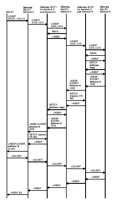
Figure 2. Multiple gateway VTAMs and back-to-back gateway NCPs
Diagram of multiple gateway VTAMs and back-to-back gateway NCPs.
Figure 3. Primary logical unit initiate, OPNDST ACQUIRE
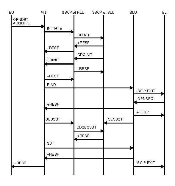
Diagram of primary logical unit initiate, OPNDST ACQUIRE.
Figure 4. Primary logical unit initiate, SIMLOGON
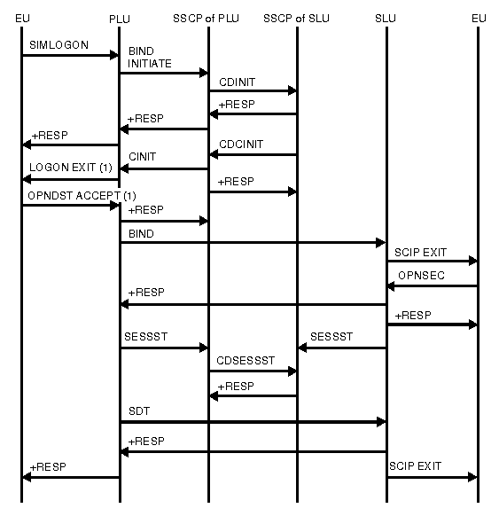
Diagram of primary logical unit initiate, SIMLOGON.
  1. LOGON EXIT and OPNDST ACCEPT flow only when the PLU is associated with an application program. It does not appear in the flow if the PLU is a device-type logical unit. This is true for many following flows with LOGON EXIT and OPNDST ACCEPT.
Figure 5. Primary logical unit initiate, SIMLOGON(RELREQ)
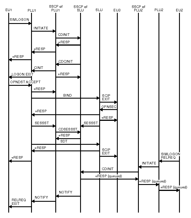
Diagram of primary logical unit initiate, SIMLOGON(RELREQ).
Figure 6. Primary logical unit initiate, SIMLOGON(RELREQ): Session is pending active or already in progress
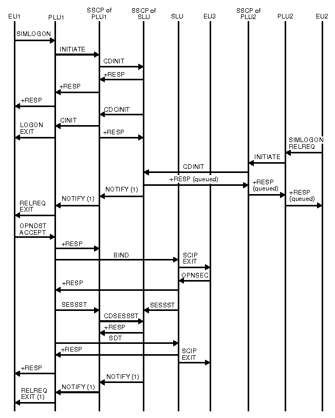
Diagram of primary logical unit initiate, SIMLOGON(RELREQ): Session is pending active or already in progress.
  1. If the session is pending active, the NOTIFY request and the RELREQ EXIT request flow after the response to the CDINIT request from the PLU2 SSCP. If the session is already in progress, these requests flow after the response to the OPNDST ACCEPT.
Figure 7. Independent PLU initiating cross-domain session with independent SLU
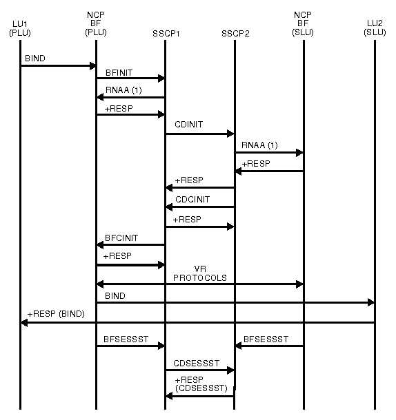
Diagram of independent PLU initiating cross-domain session with independent SLU.
  1. RNAA flows only if the network address is needed.
Figure 8. Dependent PLU initiating cross-domain session with independent SLU
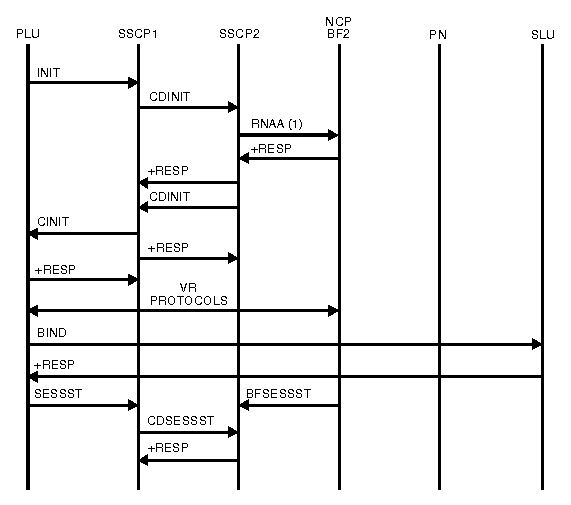
Diagram of dependent PLU initiating cross-domain session with independent SLU.
  1. RNAA flows only if the network address is needed.
Figure 9. PLU initiating request for single gateway VTAM and single gateway NCP
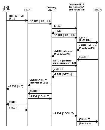
Diagram of PLU initiating request for single gateway VTAM and single gateway NCP.
Note: Session setup continues as in the flow for a SLU-initiated session.
Figure 10. Independent PLU requesting session with independent SLU through single gateway VTAM and single gateway NCP
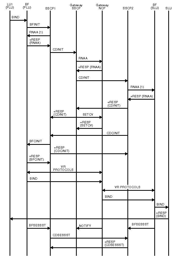
Diagram of independent PLU requesting session with independent SLU through single gateway VTAM and single gateway NCP.
  1. RNAA flows only if the network address is needed.
Figure 11. PLU-initiated request setup queued for single gateway NCP and single gateway VTAM
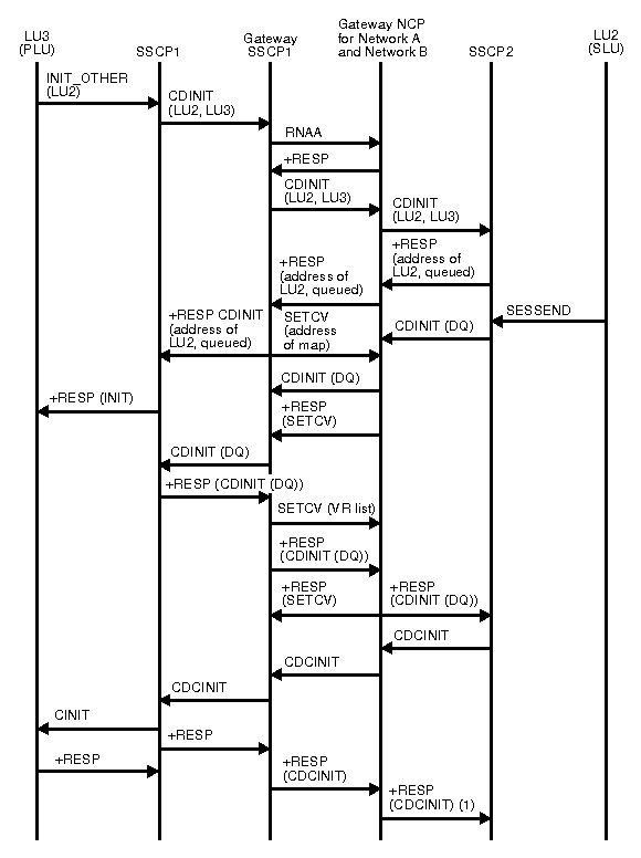
Diagram of PLU-initiated request setup queued for single gateway NCP and single gateway VTAM.
  1. Session setup continues as in the flow for an SLU-initiated session.
Figure 12. Secondary logical unit initiate (LOGON)
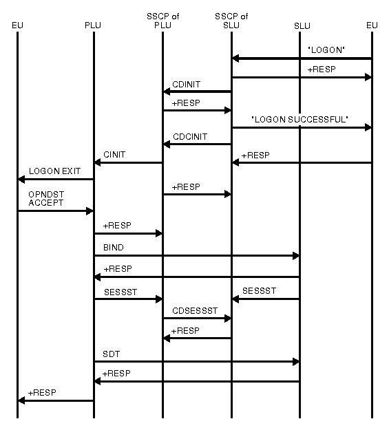
Diagram of secondary logical unit initiate (LOGON).

Figure 13. Secondary logical unit initiate (REQSESS)
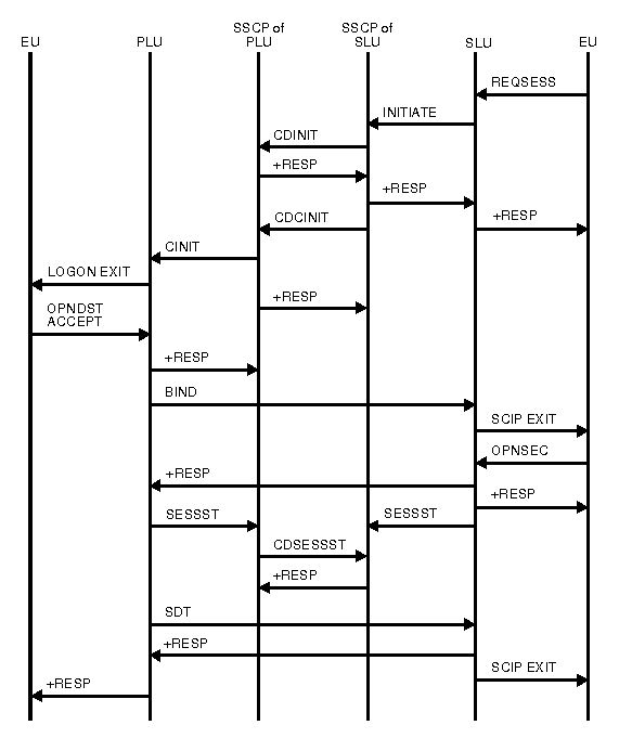
Diagram of secondary logical unit initiate (REQSESS).
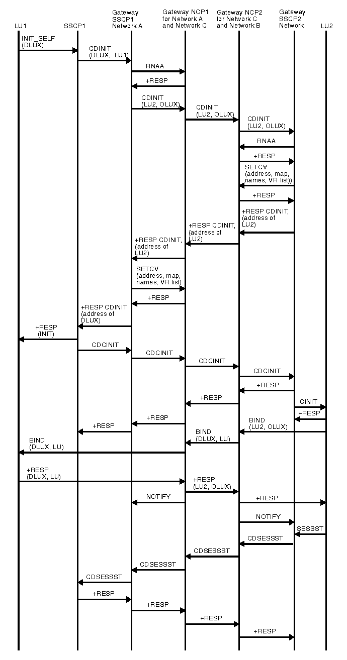
Figure 14. Secondary logical unit initiate (INIT SELF)
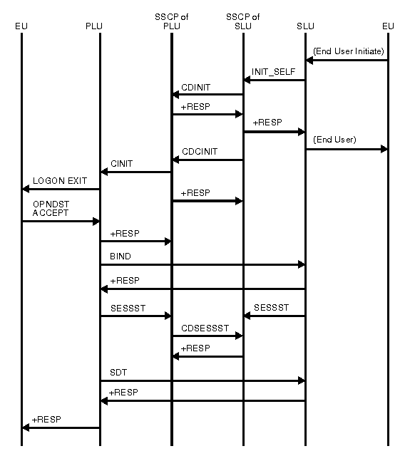
Diagram of secondary logical unit initiate (INIT SELF).
Figure 15. Sending an unformatted request to the SSCP
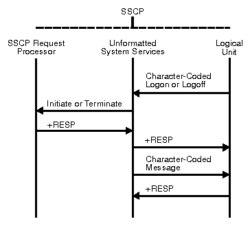
Diagram of sending an unformatted request to the SSCP.

In this example, the logical unit sends a character-coded logon or logoff to the SSCP. The unformatted system services portion of SSCP converts the logon into a field-formatted Initiate Self or Terminate Self request. The request is then passed to the SSCP request processor.

If the return code indicates an unsuccessful transmission, the unformatted system services portion of SSCP converts the request into a form that can be understood by the terminal logical unit.

Figure 16. Dependent SLU initiating a cross-domain session with application LU
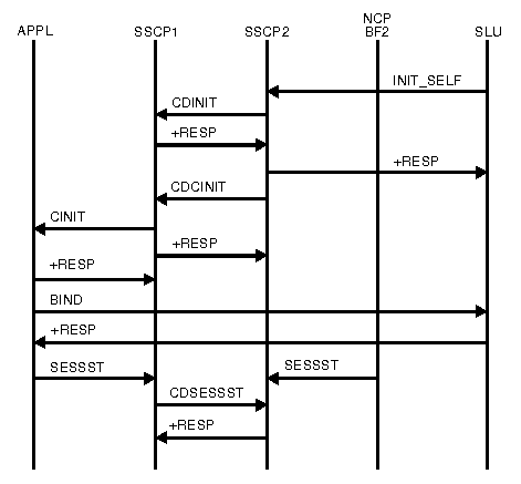
Diagram of dependent SLU initiating a cross-domain session with application LU.
Figure 17. SLU initiating request for single gateway VTAM and single gateway NCP
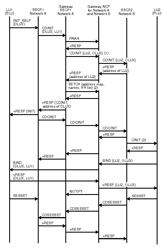
Diagram of SLU initiating request for single gateway VTAM and single gateway NCP.
  1. LU1 is initiating a session with DLUX. Using alias name translation, SSCP1 translates DLUX to LU2 and LU1 to OLUX.
  2. Names are sent to allow substitution in the BIND.
  3. The CINIT drives the logon exit.
Figure 18. SLU initiating request for single gateway connecting three or more networks
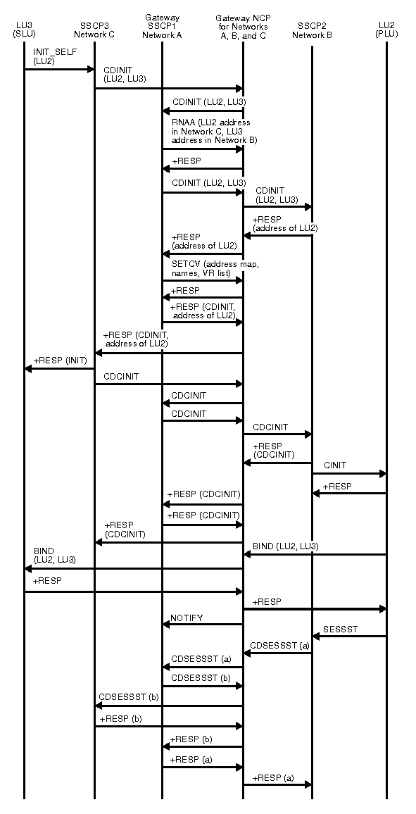
Diagram of SLU initiating request for single gateway connecting three or more networks.
Figure 19. SLU initiating request for predesignated control of gateway NCP by middle host (part 1 of 2)
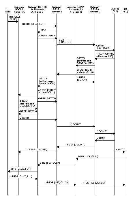
Diagram of SLU initiating request for predesignated control of gateway NCP by middle host.
Figure 20. SLU initiating request for predesignated control of gateway NCP by middle host (part 2 of 2)
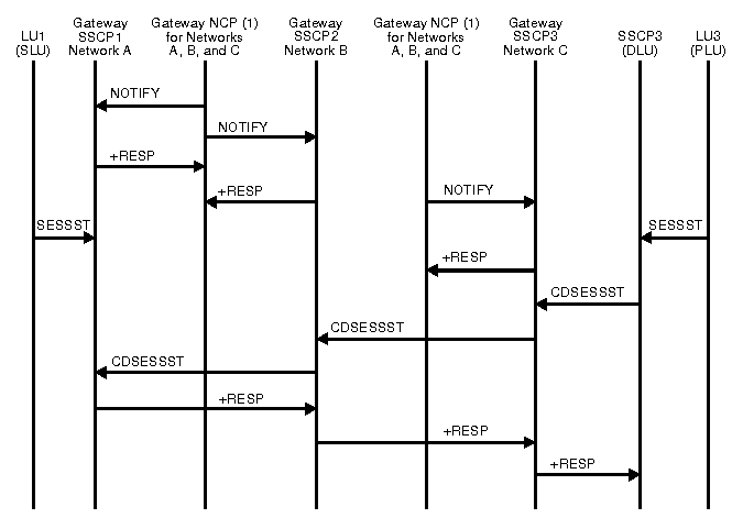
Diagram of SLU initiating request for predesignated control of gateway NCP by middle host.
  • To simplify the flow, the gateway NCP is shown twice in this flow.
Figure 21. Third party initiating CLSDST PASS
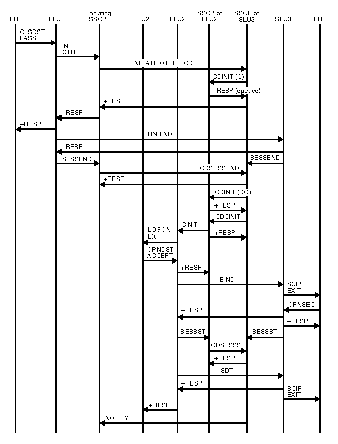
Diagram of third party initiating CLSDST PASS.
Figure 22. Third party initiating CLSDST PASS with NOTIFY
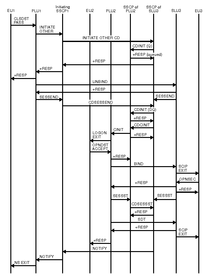
Diagram of third party initiating CLSDST PASS with NOTIFY.
Figure 23. Third party initiating request spanning three networks
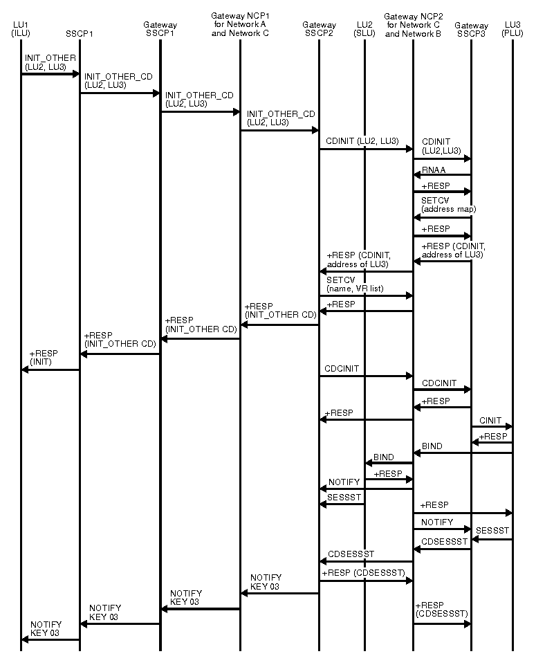
Diagram of third party initiating request spanning three networks.
Figure 24. Initiating session using VARY NET,LOGON or LOGAPPL
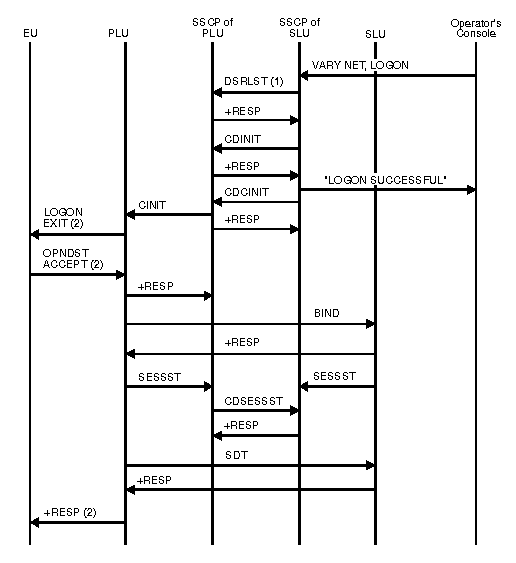
Diagram of initiating session using VARY NET,LOGON or LOGAPPL.
  1. Optional; occurs only when SLU is a dial device.
  2. This applies only when the PLU is associated with an application program. It does not appear in the flow if the PLU is a device-type logical unit.
Figure 25. Notification of PLU availability for autologon
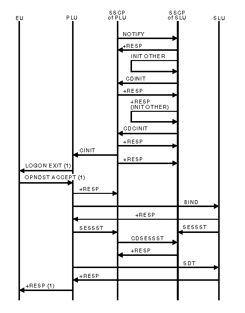
Diagram of notification of PLU availability for autologon.
  1. This applies only when the PLU is associated with an application program. It does not appear in the flow if the PLU is a device-type logical unit.
Figure 26. Failure (CDINIT rejection) of session initiated by an SLU for single gateway VTAM and single gateway NCP
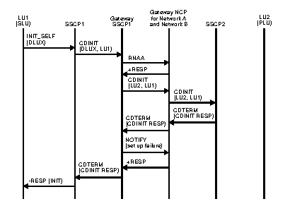
Diagram of failure (CDINIT rejection) of session initiated by an SLU for single gateway VTAM and single gateway NCP.
Figure 27. Failure (SETCV failure) of session initiation by an SLU for single gateway VTAM and single gateway NCP
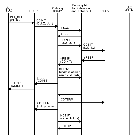
Diagram of failure (SETCV failure) of session initiation by an SLU for single gateway VTAM and single gateway NCP.
Figure 28. Failure (CINIT rejection) of setup procedure initiated by an SLU for single gateway VTAM and single gateway NCP
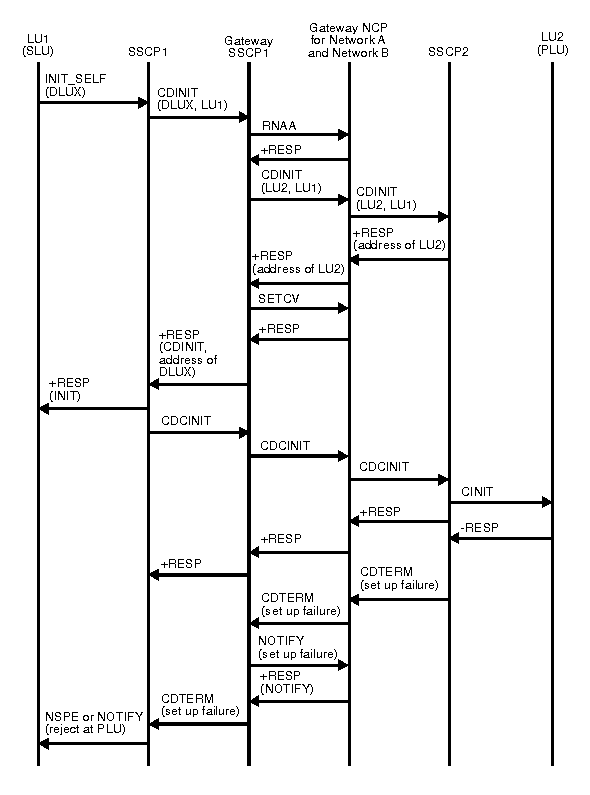
Diagram of failure (CINIT rejection) of setup procedure initiated by an SLU for single gateway VTAM and single gateway NCP.

Go to the previous page Go to the next page


Copyright IBM Corporation 1990, 2014