When you create a CICS® topology
for the application, separate the application into components for
presentation, business logic, and data access.
Before you begin
To follow the scenario, you must have an application that
runs in a single CICS region.
This scenario uses the general insurance application, which is initially
set up to run in a single region. To use the general insurance application,
you must have completed the setup as described in The general insurance application.
About this task
Using a topology has the following benefits:
You can create a highly available application
You can introduce workload management
You can scale the application by cloning additional regions to
cope with an increase in throughput
To create a simple topology, create three CICS regions: a terminal-owning region (TOR),
an application-owning region (AOR), and a data-owning region (DOR).
You can use MRO or IPIC connections between the CICS regions, but MRO is faster when the regions
are in the same sysplex. You do not have to change the database or
VSAM files.
In this scenario, you can reuse the existing region
that contains the application as the TOR. You can copy the startup
JCL and edit it to change the system initialization parameters; for
example, the TOR does not require a connection to DB2® so you can remove the DB2CONN system
initialization parameter.
Procedure
Run the @CDEF122 job to create the
definitions for the topology in the shared CSD.
Copy and edit the JCL for the stand-alone region to create
a TOR, an AOR, and a DOR.
The JCL is already configured
to use the named counter pool that is required by the application.
In each copy of the JCL, add the application load library
to the DFHRPL concatenation:
userid.CB12.LOAD
In the JCL for the TOR, add the following system initialization
parameter values:
GRPLIST=(DFHLIST,TORLIST)
DB2CONN=NO
ISC=YES
You can reuse the existing stand-alone region as the TOR
if preferred.
In the JCL for the AOR, add the following system initialization
parameter values:
GRPLIST=(DFHLIST,AORLIST)
DB2CONN=NO
ISC=YES
In the JCL for the DOR, add the following system initialization
parameter values:
GRPLIST=(DFHLIST,DORLIST)
ISC=YES
DB2CONN=YES
Split the application across the regions. Put the presentation
layer in the TOR, the business logic in the AOR, and the data management
in the DOR. The PROGRAM resources in each region have a remote system
with the name of the connection to access parts of the application
over the network.
The general insurance application is
already componentized to run in different regions. For your own applications,
you might need to work with the application developer and architect
to ensure that the application can run across CICS regions in this way.
Create connections between the CICS regions:
In the TOR, create CONNECTION and SESSIONS definitions
with the name AOR1 to point to the AOR.
Set the following
attributes on the CONNECTION definition:
In the AOR, create CONNECTION and SESSIONS definitions
with the name TOR1 to point to the terminal-owning region, and CONNECTION
and SESSIONS definitions with the name DOR1 to point to the DOR.
Set the following attributes on the CONNECTION definition
for the TOR:
Log in to the TOR and run the transaction SSC1 to inquire
on some customer records.
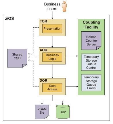
Results
The application request goes through the CICS regions in the topology and accesses VSAM
and DB2. The resulting architecture
is represented in the following diagram:Figure 1. CICS topology connected by MRO
What to do next
Although the application is running in a CICS topology, each region has static definitions
that must be manually updated. In addition, no workload management
can occur. By managing the CICS regions
with CICSPlex® SM, you can
add workload management to replace the static definitions with dynamic
routing. You can also add regions to scale the topology, providing
additional resiliency in the CICSplex.