Water delivery specifications for secondary loops
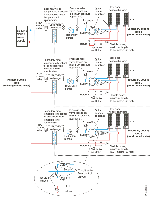
The delivery system secondary loop provides chilled water to the heat exchanger. The secondary loop consists of the components listed.
This topic describes the various hardware components that make up the delivery system secondary loop that provides the chilled, conditioned water to the heat exchanger. The delivery system includes pipes, hoses and the required connection hardware to attach to the heat exchanger. Hose management on raised or non-raised floor environments is also described.
- Comply with ISO
4126-1Note: Perform a search for ISO 4126-1.
- Be installed so that it is easily accessed for inspection, maintenance, and repair.
- Be connected as close as possible to the device that it is intended to protect.
- Be adjustable only with the use of a tool.
- Have a discharge opening that is directed so that discharged water or fluid will not create a hazard or be directed toward any person.
- Have an adequate discharge capacity to ensure that the maximum working pressure is not exceeded.
- Be installed without a shutoff valve between the overpressure safety device and the protected device.
The primary cooling loop is considered to be the low temperature building chilled-water supply or a modular chiller unit. The primary loop must not be used as a direct source of coolant for the heat exchanger for two main reasons. First, below-dew-point water will cause air moisture to form on the door heat exchanger as it operates (condensation will drip and gather under the rack). Second, if proper leak detection is not established (for example, monitored leak tape, hose-in-trough with leak sensors and automatic shut-off valves) and a leak in the door, hoses or manifolds occurs, the constant, large supply of primary loop water could result in large amounts of water leaking into the data center. Water provided in a controlled and monitored secondary, closed loop, would limit the amount of water available in a leak situation, and prevent condensation from forming.
- Couplings to match those provided on the heat exchanger
- Flexible hoses
- Thermal feedback to a flow valve that will adjust and control supply water temperature
- Pressure relief valve
- Shutoff valves for each line running to a door
- Adjustable flow valves for each supply line to a door
Manifolds and piping
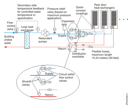
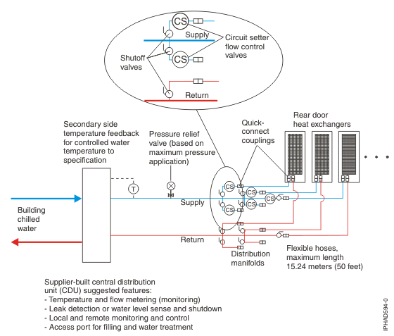
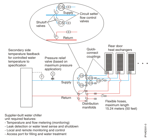
Manifolds that accept large-diameter feed pipes from a pump unit are the preferred method for splitting the flow of water to smaller diameter pipes or hoses that are routed to individual heat exchangers. Manifolds must be constructed of materials compatible with the pump unit and related piping. See Water specifications for the secondary cooling loop. The manifolds must provide enough connection points to allow a matching number of supply and return lines to be attached and the manifolds must match the capacity rating of the pumps and heat exchanger (between the secondary cooling loop and building chilled-water source). Anchor or restrain all manifolds to provide the required support to avoid movement when quick-connect couplings are plugged to the manifolds and when valves are opened or closed.
Example manifold supply pipe sizes
- Use a 50.8 mm (2 in.) supply pipe to provide the correct flow to six (100 kW CDU) 19 mm (0.75 in.) supply hoses.
- Use a 63.5 mm (2.50 in.) supply pipe to provide the correct flow to eight (120 kW CDU) 19 mm (0.75 in.) supply hoses.
- Use an 88.9 mm (3.50 in.) supply pipe to provide the correct flow to twenty (300 kW CDU) 19 mm (0.75 in.) supply hoses.
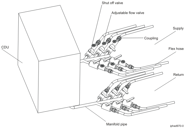
Shutoff valves are suggested for each supply and return line that exits the manifold to allow stopping the flow of water in individual lines of multiple circuit loops. This provides a way of servicing or replacing an individual heat exchanger without affecting the operation of other heat exchangers in the loop.
Adjustable flow valves (called circuit setters) are also suggested for each supply line that exits a supply manifold so changes can be made to the flow to each individual rack, in the event that door heat exchangers are added or removed from the secondary loop (this method keeps water flow within specification to each door heat exchanger).
Temperature and flow metering (monitoring) are suggested in secondary loops, to provide assurance that water specifications are being met and that the optimum heat removal is taking place.
Anchor or restrain all manifolds and pipes to provide the required support, and to avoid movement when quick-connect couplings are being attached to the manifolds.
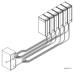
The following figure shows an example of a typical central manifold layout that supplies water to multiple heat exchangers.
The following figure shows another layout for multiple water circuits.
The following figure shows an extended manifold layout.
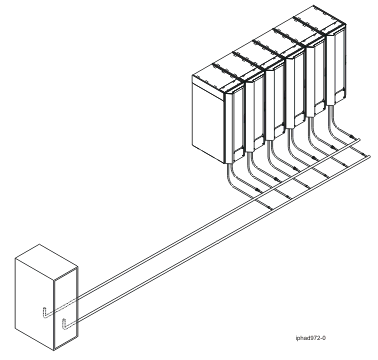
Flexible hoses and connections to manifolds and heat exchangers
Pipes and hose configurations can vary and are determined by analyzing the needs of your facilities, or a site preparation representative can provide this analysis.
Flexible hoses are needed to supply and return water between your hard plumbing (manifolds and cooling distribution units) and the heat exchanger, (allowing needed movement when opening and closing the rack rear door).
Hoses are available that provide water with acceptable pressure-drop characteristics and that help prevent depletion of some corrosion inhibitors. These hoses must be made of Ethylene Propylene Diene Monomer (EPDM) rubber - peroxide cured, non-metal oxide material and will have Parker Fluid quick-connect couplings at each end. These couplings are defined below and are compatible with the heat exchanger couplings. Hose lengths from 3 - 15 m (10 - 50 ft), in increments of 3 m (10 ft) are available. Hoses longer than 15 m (50 ft) may create unacceptable pressure loss in the secondary circuit and reduce the water flow, and thus reduce the heat removal capabilities of the heat exchanger.
For a suggested supplier of these hoses, see the table in Miscellaneous parts supplier. Use solid piping or tubing that has a minimum inner diameter of 19 mm (0.75 in.) and the least number of joints possible between a manifold and a heat exchanger in each secondary loop.
Quick-connect couplings are used to attach the hoses or fixed pipes to the distribution manifolds and the rear door heat exchangers. Hose couplings that attach to the heat exchanger must have the following characteristics.
- The couplings should be constructed of passivated 300-L series stainless steel or brass couplings with less than 30 percent zinc content. The coupling size is 19 mm (0.75 in.).
- The supply hose must have a Parker (male) quick-coupling nipple part number SH6-63-W, or equivalent. The return hose must have a Parker (female) quick-conect couplings part number SH6-62-W, or equivalent.
- At the opposite (manifold) end of the hoses, it is suggested that similar quick-connect couplings be used. However, if other types are desired, it is also suggested that positive locking mechanisms be used to prevent loss of water when the hoses are disconnected. The connections must minimize water spill and air inclusion into the system when they are disconnected.