Hardware specifications provide detailed information for your rack, including dimensions, electrical, power, temperature, environment, and service clearances.
Note: Before installing rear door heat exchangers on your 7014-T42 rack, see the Planning for the installation of rear door heat exchangers chapter
of the Site Preparation and Physical Planning Guide, SA76-0103.
| Dimensions | |||
| Height | 2015 mm (79.3 in.) | ||
| Capacity | 42 usable EIA units | ||
| Height with PDP - DC only | Not applicable | ||
| Width without side panels | 623 mm (24.5 in.) | ||
| Width with side panels | 644 mm (25.4 in) | ||
| Depth with back door only | 1042 mm (41.0 in.) | ||
| Depth with back door and front door | 1098 mm (43.3 in.) | ||
| Depth with sculptured style front door | 1147 mm (45.2 in.) | ||
| Weight | |||
| Base rack (empty) | 261 kg (575 lb.) | ||
| Full rack | 930 kg (2045 lb.) See 7014-T00, 7014-T42 and 0553 rack weight distribution and floor loading |
||
| Electrical1 | (sum specified values for drawers or enclosures in rack) | ||
| DC rack voltage (nominal) | -48 V dc | ||
| Power source loading maximum in kVa2 | See power cord options for the 7014, 0551, and 0553 racks for details | ||
| Voltage range (V dc) | -40 to -60 | ||
| AC rack | 683 Btu/hr | ||
| Power source loading maximum in kVa (per PDB)3 | 135 W | ||
| Voltage range (V ac) | 200 to 240 | ||
| Frequency (Hz) | 50 or 60 | ||
| Temperature requirements | See your server or hardware specifications for specific requirements. | ||
| Humidity requirements | See your server or hardware specifications for specific requirements. | ||
| Noise emissions3 | Rack noise levels are a function of the number and type of drawers installed. See your server or hardware specifications for specific requirements. | ||
| Install or air flow | Rack airflow requirements are a function of the number and type of drawers installed4. Refer to the individual drawer specifications. | ||
| Service clearances1 | |||
| Front | Back | Sides | |
| 915 mm (36 in.) | 915 mm (36 in.) | 915 mm (36 in.) | |
Note:
|
|||
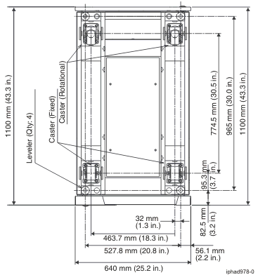
Caster and leveler locations
The following diagram provides the caster and leveler locations for the 7014-T00, 7014-T42, 0551, and 0553 racks.
Figure 1. Caster and leveler locations
