LEDs
LED colors are used consistently throughout the enclosure and its components to indicate status
- Green
- Good or positive indication
- Flashing green or amber
- Non-critical condition
- Amber
- Fault
PSU LEDs
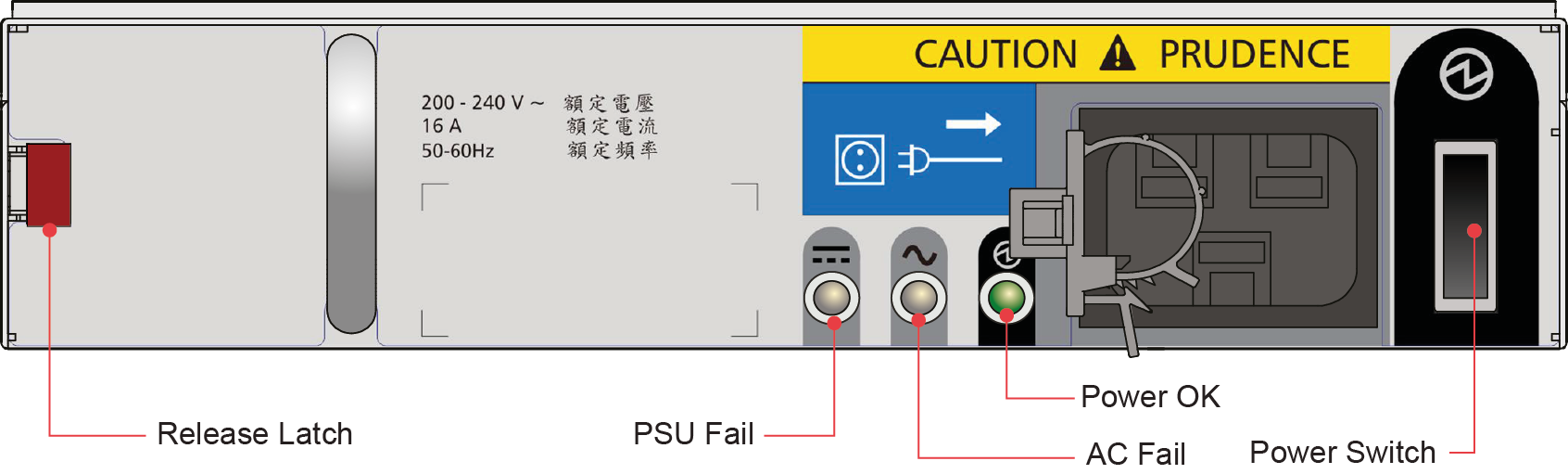
| PSU Fail (Amber) | AC Missing (Amber) | Power (Green) | Status |
|---|---|---|---|
| Off | Off | Off | No AC power to either PSU. |
| On | On | Off | PSU present, but not supplying power or PSU alert state (usually due to critical temperature). |
| Off | Off | On | Main AC present, switch on. This PSU is providing power. |
| Off | Off | Flashing | AC power present, PSU in standby (other PSU is providing power). |
| Flashing | Flashing | Off | PSU firmware download |
| Off | On | Off | AC power missing, PSU in standby (other PSU is providing power). |
| On | On | On | Enclosure management software has lost communication with the PSU. |
| On | - | Off | PSU has failed. Follow the procedure in "Replacing a Power Supply Unit (PSU)." |
Cooling module LEDs
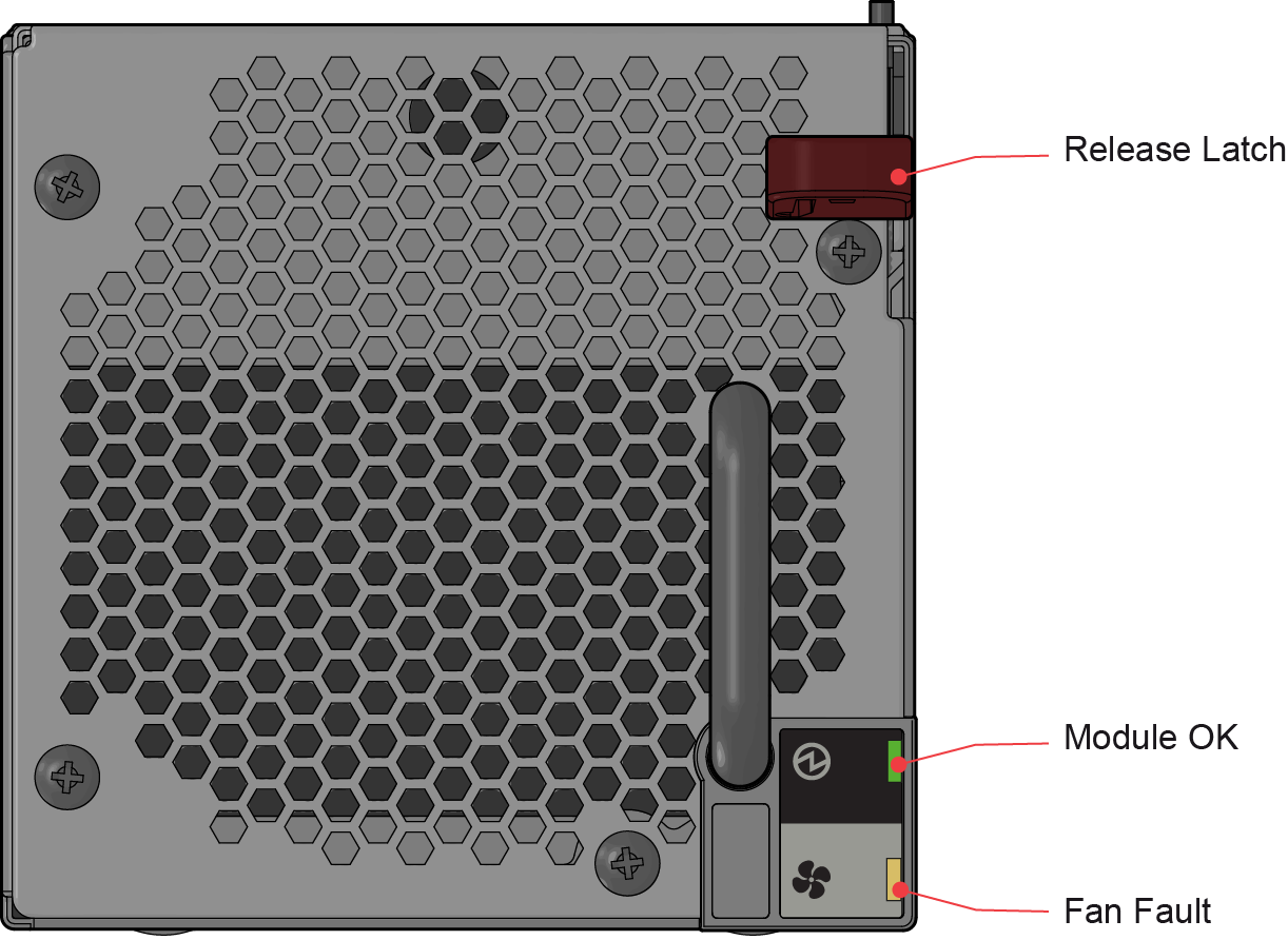
| LED | Description |
|---|---|
| Module OK | Constant green indicates that the fan is working correctly. Off means the fan has failed. Follow the procedure in "Replacing a Cooling Module." |
| Battery Fault | Not currently used. |
| Fan Fault | Amber indicates that a fan has failed. Follow the procedure in "Replacing a Cooling Module." |
Operator’s panel LEDs
The operator’s (ops) panel displays the aggregated status of all the modules, as shown in the following figure.
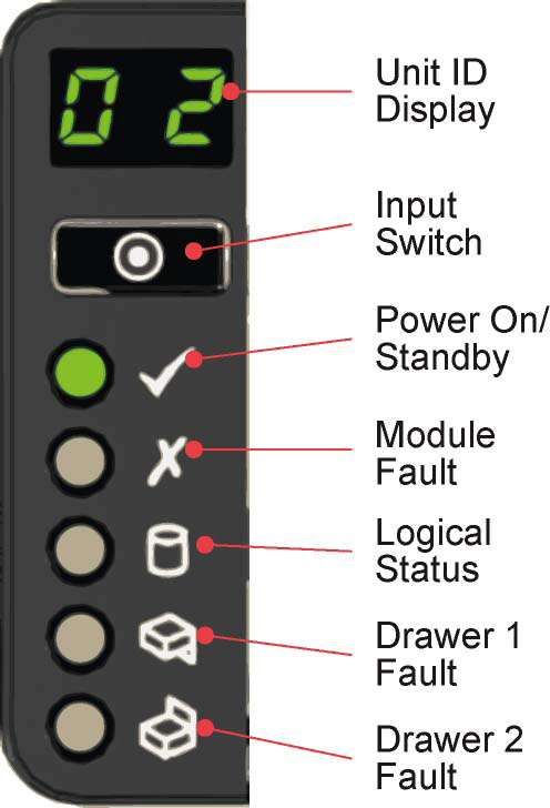
| Display/LED | Description |
|---|---|
| Unit Identification Display | Usually shows the identification number for the enclosure, but can be used for other purposes. |
| Power On/Standby LED | Amber if the system is in standby. Green if the system has full power. |
| Module Fault LED | Amber indicates a fault in a PSU, cooling module or SBB I/O module. Check the drawer LEDs to see if a drive fault is indicated (see Drawer LEDs) |
| Logical Status LED | Amber indicates a fault from something other than enclosure management usually a disk (drive fault, or Spectrum scale RAID). Check the drawer LEDs to see if a drive fault is indicated (see Drawer LEDs). |
| Drawer 1 Fault LED | Amber if there is a drive, cable, or sideplane fault in drawer 1. Open the drawer and check the disk drive LEDs for faults. |
| Drawer 2 Fault LED | Amber if there is a drive, cable, or sideplane fault in drawer 2. Open the drawer and check the disk drive LEDs for faults. |
Drawer LEDs
The following figure shows the names and locations of the disk drawer LEDs.
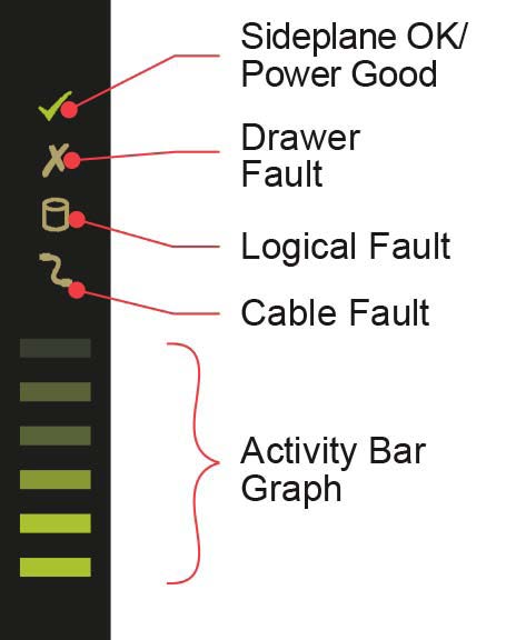
| LED | Description |
|---|---|
| Sideplane OK/Power Good | Green if the sideplane card is working and there are no power problems. |
| Drawer Fault | Amber if a drawer component has failed. If it is a drive that has failed, an amber LED lights up on the failed drive; follow the procedure in "Replacing a Disk Drive in Carrier (DDIC)." If the drives are functioning correctly, contact your storage vendor to identify the failure. |
| Logical Fault | Amber if there is a drive fault. |
| Cable Fault | Amber if the cabling between the drawer and the back of the enclosure has failed. Contact support to resolve the problem. |
| Activity Bar Graph | Shows the amount of data I/O from zero segments lit (no I/O) to all six segments lit (maximum I/O). |
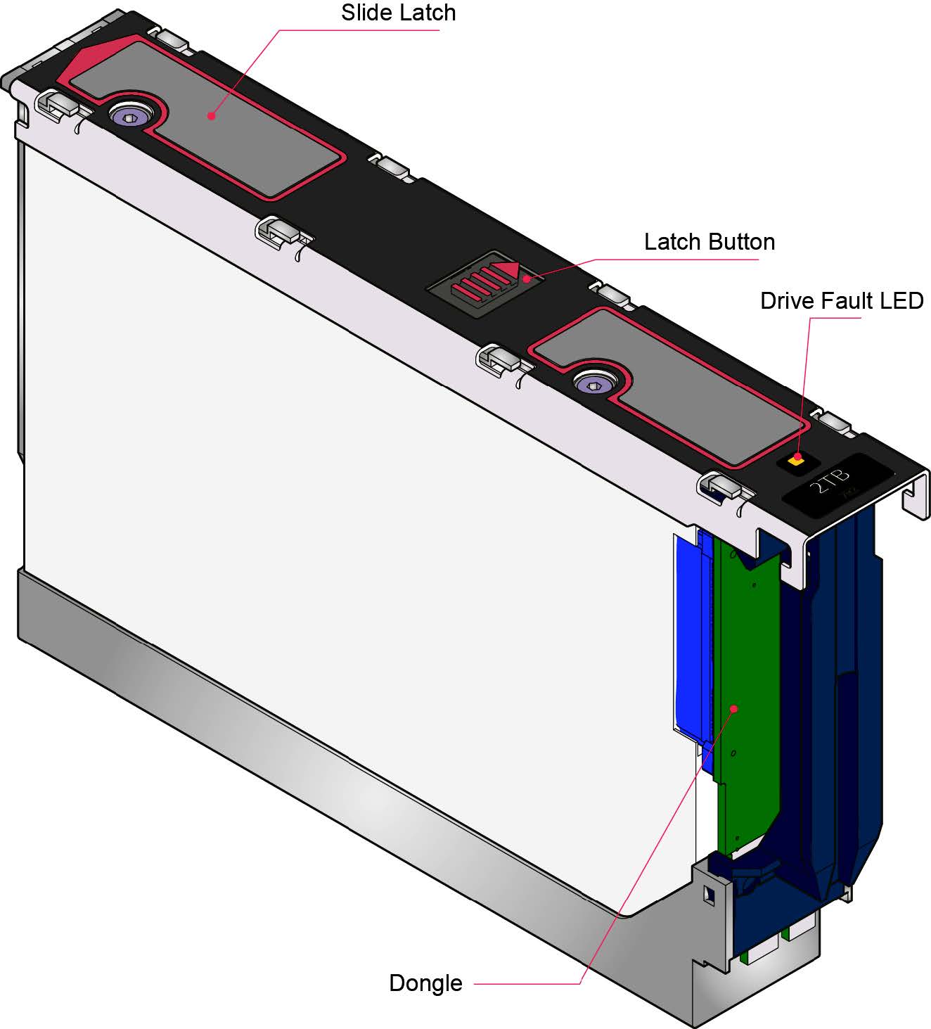
Disk drive in carrier (DDIC) LED
Each disk drive has a single amber drive fault LED as shown in the following figure. When lit, service action is required for the drive. See Elastic Storage Server Spectrum Scale RAID Administration Guide for servicing and replacing the drive. Do not remove or replace a drive without following the proper procedure stated in Elastic Storage Server Spectrum Scale RAID Administration Guide.
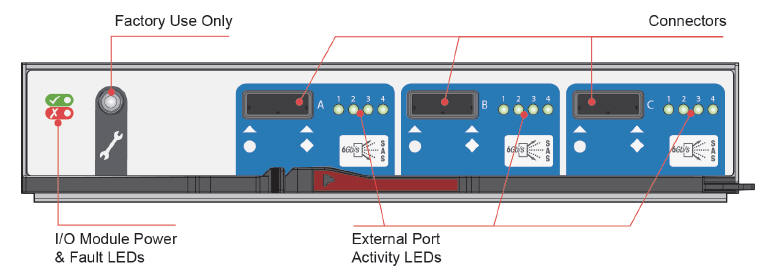
SBB I/O Module LEDs
The following figure shows the LEDs on the 6 Gb/s SAS EBOD SBB I/O module.
The LEDs on the SBB I/O module depend on the type of module in use. The following figure shows the LEDs for a common I/O module, the 6 Gb/s SAS EBOD.
| LED | Description |
|---|---|
| I/O Module OK | Constant green if the I/O module is operating correctly. Flashing green indicates an I/O module VPD error. |
| I/O Module Fault | Constant amber if the I/O module is faulty. For replacement procedure see Replacing an SBB I/O module. |
| External Host Port Activity | Constant green indicates that there is a host port connection but no activity. Flashing green indicates that there is a host port connection, and data is being transferred. |