Half height drive: No apparent failure or damage to tape
About this task
Note: If the cartridge in the drive is an INPUT tape that contains ACTIVE or 'ONLY COPY'
data (there is no backup), eject commands that are issued at the host fail to unload the tape, and
power-cycling the drive fails to eject the cartridge, make no further attempts to unload this
tape. Call Technical Support and open a PMR if one is not already
open, to initiate the process of sending the drive with the loaded cartridge in for recovery.
Procedure
- Set the drive on its left side with the head and tape path
facing up.
Figure 1. Rewinding tape into cartridge 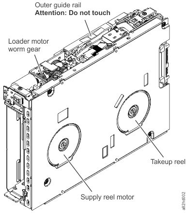
1 Loader motor worm gear 3 Takeup reel motor 2 Outer guide rail (WARNING: Do Not Touch) 4 Supply reel motor - Locate the threader intermediate gear (1)
near the rear of the drive. You can use your finger to rotate the
threader intermediate gear (1) and slowly
rotate the threader mechanism gear (2)
clockwise. This action draws the tape leader block assembly (LBA)
into the cartridge.
Figure 2. Drive with cover removed to reveal gear train. 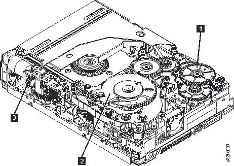
1 Threader intermediate gear 2 Threader mechanism gear 3 Loader motor worm gear - Rotate the threader motor worm gear (3)
counterclockwise until the leader block is in front of the read/write
head. This action moves the LBA out of the cartridge.
Figure 3. Leader Block Assembly (LBA) 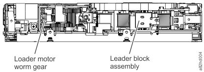
1 Loader motor worm gear 2 Leader block assembly (LBA)