Connecting cables
Procedures to connect Fibre Channel, SAS, USB, and Ethernet cables.
About this task
Connecting Fibre Channel cables
- Remove the FC port caps if necessary. Attach one end of the FC cable to port 0 on the tape
drive.
Figure 1. Full-height FC dual port 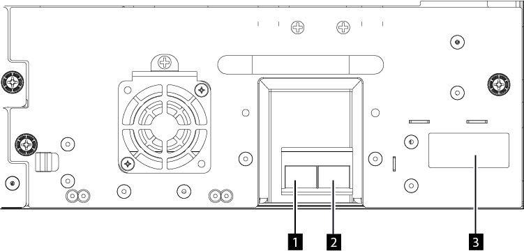
Table 1. Full-height FC dual port Number Description 1 FC port 0 2 FC port 1 3 Drive sled indicators (see Drive sled back panels) Figure 2. Half-height FC single port 
Table 2. Half-height FC single port Number Description 1 FC port 0 2 Drive sled indicators (see Drive sled back panels) - Attach the other end of the FC cable to a switch or HBA.
- Repeat the same process with port 1 if you have a dual port drive.
Connecting SAS cables
- Attach the end of the SAS cable into the connector on the HBA. If you are using a SAS fanout/Interposer cable, the end of the cable with only one connector must be plugged into the HBA.
- Connect the drive end of the cable.
- If you are using a cable with a single connector on each end, attach the other end into the connector on the tape drive.
- If you are using a SAS fanout/Interposer cable, attach one mini-SAS connector into the connector on each tape drive. The unused ends of the SAS fanout/Interposer cable are single channel and not suitable for use with disk arrays. Use the other ends to connect tape drives, or coil and secure them to the rack to minimize stress on the connectors.
Figure 3. Full-height SAS dual port 
Table 3. Full-height SAS dual port Number Description 1 SAS port 0 2 SAS port 1 3 Drive sled indicators (see Drive sled back panels) Figure 4. Half-height SAS dual port 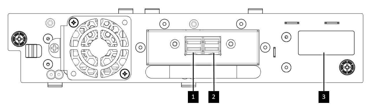
Table 4. Half-height SAS dual port Number Description 1 SAS port 0 2 SAS port 1 3 Drive sled indicators (see Drive sled back panels)
Important: SAS signal rates require clean connections between the HBA
and tape drive. Do not use adapters or converters between the HBA and the tape drive. For reliable
operation, use a SAS cable length of maximum 6 meters for 6 Gbps or slower SAS speed. For 12 Gbps SAS speed, use a SAS cable length of
maximum 3 meters.
Connecting USB cables
Two USB ports are on the library, one in the front and
one in the rear. USB connections are used by service personnel for diagnostic and service
procedures. Attach one end of the USB cable to your notebook or other device and the other end to
the front or rear USB port of the library.
Important: USB cable lengths of more than 3
meters are NOT supported for the front or rear USB ports.
Connecting Ethernet
cables
To
use the Management GUI, connect an Ethernet cable from the bottom Ethernet port on the Base Module
controller to your network. See Rear panel for the
location of the Ethernet ports.
Remember: Ethernet port A (bottom Ethernet port) is the
primary port. The second Ethernet port, Port B, is for redundancy.