Seven-segment display sequence codes and their causes
If an error occurs during the ESM boot process and the Needs Attention LED is on, the numeric display shows diagnostic information as a sequence of two-digit diagnostic codes.
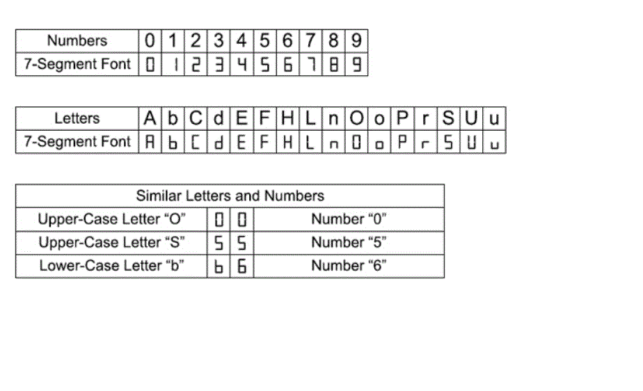
The following
figure shows the seven-segment alphanumeric characters.
Figure 1. Seven-segment
alphanumeric characters

The following table lists the sequence category codes and their associated detail codes.
Startup errors and operational states are displayed in sequences. The numeric display helps to identify a component failure. Table 1 lists the different sequences and the corresponding errors.
| Category | Category code | Detail codes |
|---|---|---|
| Startup Error | SE+ |
|
| Operational State | OS+ | |
| Component Failure | CF+ | Hx+ Host card (x = location) |
| Category Delimiter | dash+ | Separator between category-detail code pairs (See notes 3 and 4) |
| End-Of-Sequence Delimiter | blank- | End-of-sequence indicator (See notes 5 and 6) |
Notes:
|
||
| Repeating sequence | Startup and operational error |
|---|---|
| Operational failure: | |
| OS+ OH+ blank- | The processor temperature exceeds the warning level |
| Power-on diagnostic failure: | |
| SE+ dF+ blank- | Failure of a component that is not a field replaceable unit is detected |
| SE+ dF+ dash+ CF+ Hx+ blank | Failure of a host interface card is detected |
The following tables list the ESM diagnostic codes.
| Value | Description |
|---|---|
| FF | ESM Boot Diagnostic is running |
| 88 | This ESM is being held in Reset by the other ESM |
| AA | ESM-A application is booting up |
| bb | ESM-B application is booting up |
| L0 | Mismatched ESM types |
| L2 | Persistent memory errors |
| L3 | Persistent hardware errors |
| L9 | Over Temperature |
| LL | Cannot read midplane EEPROMs |
| LP | Missing Drive Port Mapping table |
| Ln | ESM not valid for enclosure |
| H2 | Invalid/Incomplete Configuration |
| LF | Lockdown with limited SYMbol support |
| LH | Controller firmware mismatch |
| H3 | Maximum Reboot Attempts Exceeded |
| H4 | Cannot Communicate with Other ESM |
| H5 | Midplane Harness Failure |
| H6 | Firmware Failure |
| H9 | Non-Catastrophic HW. ESM operational, but in a degraded mode |
| J0 | Incompatible module |