Removing the base function system backplane from the 8247-42L, 8286-41A, or 8286-42A
Learn how to remove the base function system backplane from a server to replace a failing part or as part of another service procedure.
To complete this procedure, you must have prepared the system to remove and replace the base function system backplane. For instructions, see Preparing the system to remove and replace the base function system backplane.
To remove the base function system backplane, complete the following steps:
- Remove the cover from the front SAS cable. Grasp the handle (A) and
pull away from the side of the system, then slide the cover toward
the rear to remove it as shown in Figure 1. Figure 1. Removing the SAS cables cover

- Label the front SAS cables, paying attention to the connectors
each cable attaches to on the disk drive backplane and the SAS RAID
internal adapter. Disconnect the front SAS cables from the disk drive
backplane by pressing the latch (A) and unplugging
the cable as shown in Figure 2. Figure 2. Disconnecting the front SAS cables

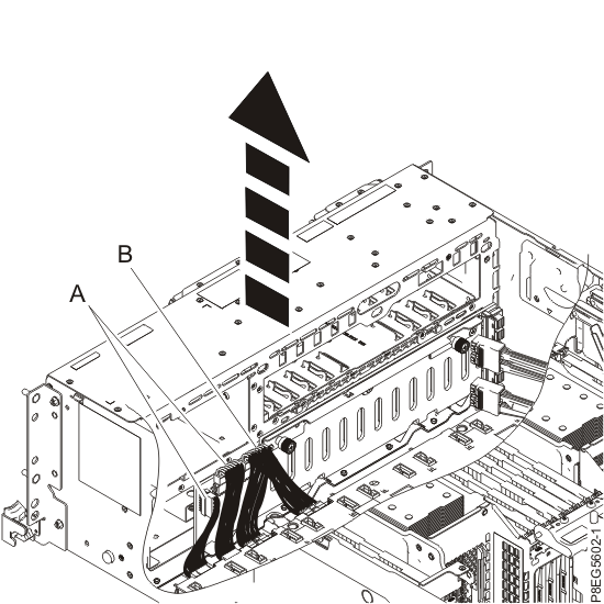
- Label and remove the signal, and control panel cables (A),
and the power Y cable (B), from the disk drive
backplane and system backplane. Refer to Figure 3. Figure 3. Removing the power, signal, and control panel cables
- Remove the disk drive backplane. Figure 4. Removing the disk drive backplane

- Remove the USB cable cover on the side of the system chassis.
Grasp the top handle of the cover and pull out and away from the side
of the chassis. Push the cover toward the rear of the system until
the slots on the cover clear the pins on the side of the chassis,
then remove the cover. See Figure 5. Figure 5. Removing the USB cable cover

- Disconnect the front USB cable from the system backplane
and route it over the side of the system and out of the way to provide
clearance for removing the system backplane. See Figure 6. Figure 6. Disconnecting the front USB cable
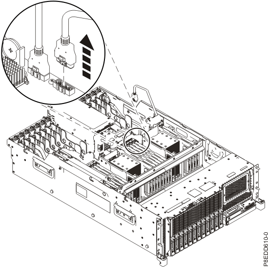
- Disconnect and remove the power distribution signal cable (A) from
the rear of the power supply assembly and the system backplane connector.
See Figure 7. Figure 7. Removing the power distribution signal cable

- If your system is an 8247-42L, label and remove
any graphics processing unit (GPU) adapters that are installed in
PCIe adapter slot locations C3 and C6. Otherwise, skip this step.
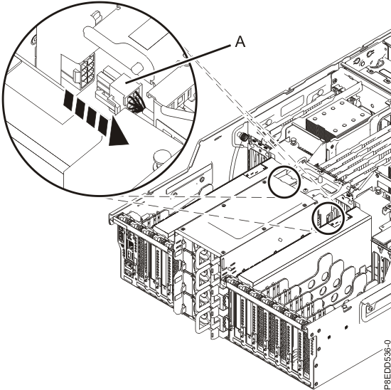
- Disconnect the adapter power cable (A) from
the power distribution board. See Figure 8. Figure 8. Disconnecting the GPU adapter power cable
- Remove the rear shield by pulling out the two plastic
push-pins (A), then tilt the shield up to remove
it. See Figure 9. Figure 9. Removing the GPU adapter rear shield

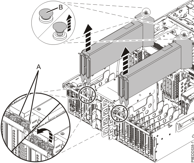
- Open the adapter latch (A) at the target slot by rotating the latch
(A) at the rear of the system, in the direction shown. Pull up the locking
latch (B) in the direction that is shown and remove the GPU adapter from its
slot. See Figure 10. Figure 10. Removing the GPU adapter
- Disconnect the adapter power cable (A) from
the power distribution board. See Figure 8.
- Remove the PCI adapter dividers. Note: The PCI adapter divider between PCI adapter slots P1-C1 and P1-C2 is unique and has three light pipes. This divider must be replaced into the same location.
- Repeat step 21 for removing
the remaining PCI adapter dividers. Figure 11. Removing the PCI adapter dividers

- Repeat step 21 for removing
the remaining PCI adapter dividers.
- If your system is an 8286-41A and the plastic
air flow assembly is covering one of the system backplane screws,
remove the plastic air flow assembly to access the screw, otherwise
skip this step.
- Grasp and lift the air duct, as shown in Figure 12. Figure 12. Removing the air duct
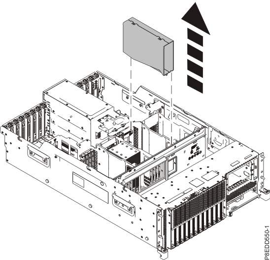
- Remove the front inner guide by carefully prying the
top, side, and bottom edges away from the sheetmetal opening with
a flat blade screwdriver. Pull the guide out of the opening, and lift
out of the system, as shown in Figure 13. Figure 13. Removing the front inner guide

- Remove the front baffle bracket by pushing the bracket
through the hole (A) in the sheetmetal with
a screwdriver, then slide the bracket to left and pull the bracket
away from the sheetmetal, as shown in Figure 14. Figure 14. Removing the front baffle bracket

- Grasp and lift the air duct, as shown in Figure 12.
- If your system is an 8286-41A, you must remove the
rear air baffle and rear air baffle guide so that they can be installed on the replacement system
backplane during the replace procedure. If your system is not an 8286-41A, skip this step.
- Remove the three screws that secure the top cover attach bracket by using a T-10 Torx driver.
Then, remove the top cover attach bracket, as shown in Figure 15. Figure 15. Removing the top cover attach bracket

- Grasp and lift the rear air baffle, as shown in Figure 16. Figure 16. Removing the rear air baffle
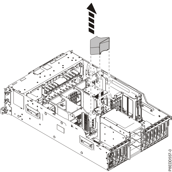
- Remove the rear air baffle guide by pressing the rear air baffle guide latch and lifting the
rear air baffle guide, as shown in Figure 17. Figure 17. Removing the rear air baffle guide

- Install the top cover attach bracket. Then, install and tighten the three screws that secure
the top cover attach bracket by using a T-10 Torx driver, as shown in Figure 18. Figure 18. Installing the top cover attach bracket

- Remove the three screws that secure the top cover attach bracket by using a T-10 Torx driver.
Then, remove the top cover attach bracket, as shown in Figure 15.
- Remove the system backplane.
- Using a Phillips screwdriver, unscrew and remove two
silver screws (B) as shown in Figure 19. Figure 19. Location of system backplane screws

- Slide the system backplane in the direction that is
shown in Figure 20,
then lift it up to remove it. Place the system backplane on an ESD
surface. Figure 20. Removing the system backplane
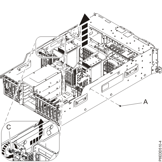
- Using a Phillips screwdriver, unscrew and remove two
silver screws (B) as shown in Figure 19.
