Replacing the system backplane in the 8335-GTW
To replace a system backplane, complete the steps in this procedure.
Procedure
-
Using the blue handles (A), lower the system backplane
(B) into the system.
Figure 1. Lowering the system backplane into the system 
-
Replace the three metal pipe supports at (B) (two smaller supports) and
(C) (one longer support). Align and tighten the 22 screws into the
system backplane at (A) and into the pipe supports at
(B) and (C).
The screw locations are shown in Figure 2. The screws at (A) are the shortest. The screws at (B) and (C) are longer and secure the pipe supports.
Figure 2. System backplane screw locations 
-
Ensure that the jumper shown in Figure 3
is set to the water cooled position.
Figure 3. Jumper in water-cooled position 
-
Replace one screw (B) on each side of the middle support
(A).
See Figure 4.
Figure 4. Replacing the middle support screws 
-
Prepare the system processor module for installation:
-
Open the latches that hold the system processor module in the supplied
removal tool (A). Push down on the ring (B) while
pressing in on the tabs (C).
See Figure 5.
Figure 5. Opening the processor removal tool latches 
-
Lower the tool over the system processor module while ensuring that the two
guide pins (A) insert into the alignment holes (B) on
each side of the tool.
See Figure 6.
Figure 6. Lowering the removal tool onto the system processor module 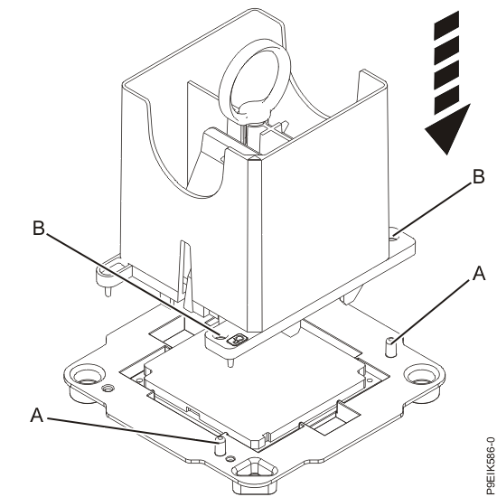
-
With the removal tool sitting on top of the system processor module, push
down on the ring (A) to close the latches (C) and lock
the system processor module into the tool. Make sure that both of the tool jaws are locked on the
system processor module.
See Figure 7.
Figure 7. Locking the system processor module into the tool 
-
Open the latches that hold the system processor module in the supplied
removal tool (A). Push down on the ring (B) while
pressing in on the tabs (C).
-
Install the system processor module:
-
If dust or debris is present on the system processor socket, use the supplied air pump to clean
the socket. Blow small bursts of air from the center toward the sides of the socket, as shown in
Figure 8.
Figure 8. Removing dust and debris from the system processor socket 
-
Lower the tool and system processor module onto the socket. Align the guide pins
(A) with the alignment holes (B) on each side of the
tool. Use care to lower the tool evenly without tilting the tool.
See Figure 9.Note: Do not attempt to slide the tool and the system processor module in any direction while the system processor module is touching the socket. If the tool and the system processor module are not aligned with the guide pins, lift the tool and the system processor module and reposition them.
Figure 9. Installing the system processor module 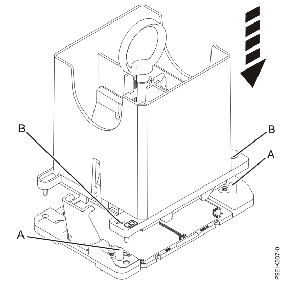
-
Open the latches that hold the system processor module in the supplied
removal tool (A). Push down on the ring (B) while
pressing in on the tabs (C).
See Figure 10.
Figure 10. Removing the system processor module tool 
-
If dust or debris is present on the system processor socket, use the supplied air pump to clean
the socket. Blow small bursts of air from the center toward the sides of the socket, as shown in
Figure 8.
-
Inspect the thermal interface material (TIM) for visible signs of damage, as shown in Figure 11. If you see folds, tears, bends, or if you have
doubts about the TIM, replace it.
Figure 11. Inspecting the thermal interface material 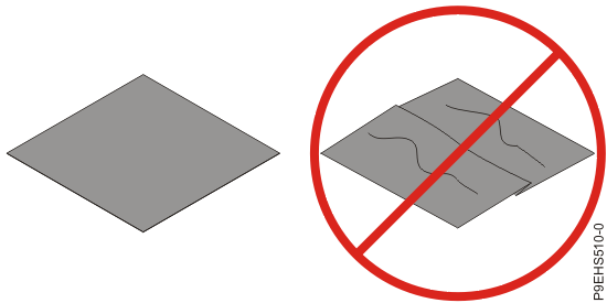
-
Use this step to install a new TIM and reuse the existing heat
sink.
-
Using the tweezers, remove the TIM from the carrier strip and center it onto the system
processor module.
The TIM has no preferred up side. The TIM can be placed on the system processor module and centered as shown in Figure 12.
Figure 12. Installing a new TIM onto the system processor module 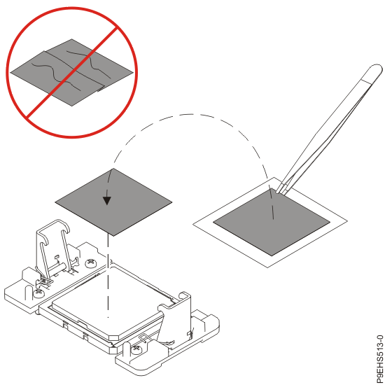
Continue with step 16.
-
Using the tweezers, remove the TIM from the carrier strip and center it onto the system
processor module.
-
Use this step to reuse the existing undamaged TIM and heat sink.
-
Using the tweezers, move the old TIM from the clean, dry surface and center it onto the new
system processor module.
The TIM has no preferred up side. The TIM can be placed on the system processor module and centered as shown in Figure 13.
Figure 13. Replacing the TIM onto the system processor module
-
Using the tweezers, move the old TIM from the clean, dry surface and center it onto the new
system processor module.
-
Replace the air baffles (A) and (B) as shown in
Figure 14.
Carefully move the baffles around the hoses.
Figure 14. Replacing the memory air baffles 