POWER7 information

Removing the 8202-E4B, 8202-E4C, 8202-E4D, 8205-E6B, 8205-E6C, or 8205-E6D vital product data card

Learn how to remove the vital product data (VPD) card.

If your system is managed by the Hardware Management Console (HMC), use the HMC to remove a VPD card. For instructions, see Removing a part by using the HMC.

If your system is managed by the IBM® Systems Director Management Console (SDMC), use the SDMC to remove a VPD card. For instructions, see Removing a part by using the SDMC.

Note: If you plan to replace the VPD card and have the replacement card, you can contact the following email address from 8 a.m. to 5 p.m. US Central Time, Monday to Friday, to obtain replacement activation codes prior to repair. You must supply the machine type and serial number, and the part number and serial number of the replacement VPD card. If you use the AIX® or Linux operating systems, contact pcod@us.ibm.com. If you use the IBM i operating system, contact icod@us.ibm.com.

If you do not have an HMC or SDMC, complete the following steps to remove the VPD card:

  1. Complete the prerequisite tasks that are described in Before you begin.
  2. Save the system identifiers:
    Note: To perform this operation, your authority level must be administrator or authorized service provider.
    1. In the ASMI Welcome page, if you have not already logged in, specify your user ID and password, and click Log in.
    2. In the navigation area, expand System Configuration > Program Vital Product Data.
    3. Select System Brand under Program Vital Product Data.
    4. Manually record the value for the system brand, which appears in the right pane.
    5. In the navigation area, select System Keywords under Program Vital Product Data.
    6. Manually record the Machine type-model, System serial number, System unique ID values. Also record the activation codes, if applicable, for the Capacity on Demand (COD) and Virtualization Engine Technologies (VET) values, which are shown in the content pane.
      Notes:
      1. If you do not know the system unique ID, contact your next level of support.
      2. You cannot boot the system until valid values are entered for all fields.
      3. You can change these entries only once.
    7. Click Save settings to update the system keywords and save them to the VPD.
  3. Turn on the blue system LED to identify the system you are working on. For instructions, see Enabling enclosure indicators.
  4. If necessary, identify the VPD card that you must replace. For instructions, see Identifying a part.
  5. Shut down the partitions and power off the system.

    This FRU cannot be serviced concurrently. Every partition must be shut down, and the system must be powered off to continue the repair. Authorization must come from the customer to shut down all running partitions and to power off the system. If the customer does not allow the partitions to be shut down or the system to be powered off, delay the service procedure. If the customer is using a secondary management console to manage the system, ensure that the customer is not powering on the system at this time.

  6. For a rack-mounted system, place the system in the service position. For instructions, see Placing the rack-mounted 8202-E4B, 8202-E4C, 8202-E4D, 8205-E6B, 8205-E6C, or 8205-E6D system into the service position.
  7. Remove the service access cover.
  8. Access the rear of the system and disconnect all power cords from the unit you are servicing.
  9. Attach the wrist strap.
    Attention:
    • Attach a wrist strap to an unpainted metal surface of your hardware to prevent electrostatic discharge (ESD) from damaging your hardware.
    • When using a wrist strap, follow all electrical safety procedures. A wrist strap is for static control. It does not increase or decrease your risk of receiving electric shock when using or working on electrical equipment.
    • If you do not have a wrist strap, just prior to removing the product from ESD packaging and installing or replacing hardware, touch an unpainted metal surface of the system for a minimum of 5 seconds.
  10. When removing the Vital product data card and there is an optional USB tape drive present, Do not remove the drive. Move the tape drive forward to gain access to the area below the drive.
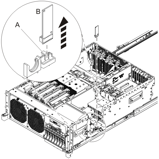
  11. Remove the VPD card.
    1. Press on the handle (A) to unlock the VPD card (B) from its slot on the system backplane. See Figure 1.
    2. Pull the VPD card out of its slot.
    Figure 1. Removing the VPD card
    Removing the VPD card


Send feedback Rate this page

Last updated: Fri, April 08, 2016