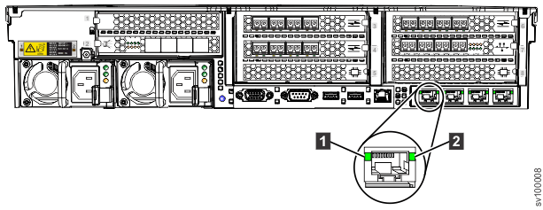
SAN Volume Controller 2145-SV1 Ethernet port LEDs
Ethernet link and activity LEDs indicate the status of each Ethernet port.
- An Ethernet-link LED indicates that the node is communicating on the network that is connected to the port.
- An Ethernet-activity LED indicates an active connection on the port.
Ethernet ports on the system board
The operator-information panel LEDs refer to the Ethernet ports that are mounted on the system board (Figure 1).

- 1 10 Gbps Ethernet port 1
- 2 10 Gbps Ethernet port 2
- 3 10 Gbps Ethernet port 3
The status of these ports is also indicated by LEDs next to each port (Figure 2).

- 1 Ethernet link LED
- 2 Ethernet activity LED
The Ethernet-link LED indicates that the node is communicating on the network that is connected to the port. The Ethernet-activity LED indicates an active connection on the port.
Ethernet ports on a 10 Gbps Ethernet adapter
If the SAN Volume Controller 2145-SV1 is equipped with a 10 Gbps Ethernet adapter, the port activity is not reflected on the activity LEDs of the operator-information panel. The activity of those ports is indicated by LEDs on the adapter itself, which are visible from the rear of the SAN Volume Controller 2145-SV1 (as shown in Figure 3). The adapter has two LEDs per port, arranged above the other. These pairs of LEDs are arranged in the same order as the ports.

- 1 10 Gbps Ethernet fault LEDs.
- 2 10 Gbps Ethernet link LEDs.
Ethernet ports on a 25 Gbps Ethernet adapter
The SAN Volume Controller 2145-SV1 node can support optional 2-port 25 Gbps Ethernet adapters. The system can support RoCE and iWARP networking adapters only for 25 Gbps iSCSI connectivity. LEDs indicate the activity on the ports on each adapter; however, the location and meaning of the LEDs differs, depending on the type of 25 Gbps card that is installed.
Figure 4 shows an example of the RoCE networking adapter. Each port on the 2-port 25 Gbps Ethernet adapter has one bi-color LED that indicates the status of the link.

Table 1 summarizes the possible values of the LEDs.
| Color | State | Meaning |
|---|---|---|
| None | Off | The port is not active. |
| Green | Solid | The port has a valid link with no active traffic. |
| Green | Flashing | The port has a valid link with active traffic. |
| Yellow | Flashing | Indicates a problem with the link. |
Figure 5 shows the 25 Gbps Ethernet host interface adapter (iWARP). Each port has a single LED that indicates the status of the port and link.

Table 2 summarizes the possible values of the LEDs on the 25 Gbps Ethernet host interface adapter (iWARP).
| Color | State | Meaning |
|---|---|---|
| Off | Off | The ports and links are not active. |
| Green | Solid | The ports have a valid link. |