Replacing the microprocessor: 2145-DH8
You can replace the microprocessor on a SAN Volume Controller 2145-DH8 node.
Before you begin
 |
or |  |
or |  |
To correctly perform this task, you need one alcohol wipe and one thermal grease syringe to replace the microprocessor. If you do not already have these items, order them before you begin to replace the part.
About this task
If the thermal-grease protective cover (for example, a plastic cap or tape liner) is removed from the heat sink, do not touch the thermal grease on the bottom of the heat sink or set down the heat sink.
Procedure
- To open the socket in preparation for inserting the microprocessor, press down and out on the
release lever ( 2 in Figure 1 as you did to remove the microprocessor, and lift the microprocessor-release lever until it stops
in the fully open position. Figure 1. Opening the SAN Volume Controller 2145-DH8 microprocessor bracket frame
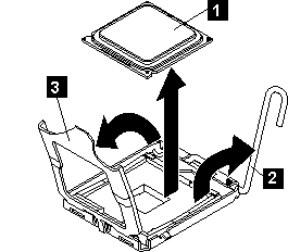
- 1 Microprocessor
- 2 Microprocessor-release lever
- 3 Microprocessor-bracket frame
- Touch the static-protective package that contains the new
microprocessor to any unpainted metal surface on the node;
then, remove the microprocessor from the package.
- Do not touch the microprocessor contacts; handle the microprocessor by the edges only. Contaminants on the microprocessor contacts, such as oil from your skin, can cause connection failures between the contacts and the socket.
- Handle the microprocessor carefully. Dropping the microprocessor during installation or removal can damage the contacts.
- Do not use excessive force when you press the microprocessor into the socket.
- Verify that the microprocessor is oriented, aligned, and positioned in the socket before you try to close the lever.
- If a plastic protective cover is on the bottom of the microprocessor, carefully remove it, as
shown in Figure 2.Figure 2. Removing the plastic protective cover from a microprocessor
- 1 Protective cover
- 2 Microprocessor
- Locate the microprocessor installation tool that comes with the new microprocessor.
- Twist the handle of the installation tool counterclockwise so that it is in the open position.
- Align the triangular alignment mark ( 4 in Figure 3) on the microprocessor installation tool with the triangle
alignment mark on the microprocessor. Then, place the microprocessor on the underside of the tool so
that the tool can grasp the microprocessor correctly onto the bottom of the installation tool.
To align the microprocessor with the socket, use the triangular alignment cutout on the microprocessor socket and the triangular alignment mark ( 4 in Figure 4) on the microprocessor. Also, use the position of the notches to align the microprocessor.
- Twist the handle of the installation tool clockwise to secure
the microprocessor in the tool. Note: You can pick up or release the microprocessor by twisting the microprocessor installation tool handle.
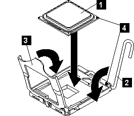
- Carefully align the microprocessor installation tool over the
microprocessor socket. Twist the handle of the microprocessor tool
counterclockwise to insert the microprocessor into the socket. Attention: The microprocessor fits only one way on the socket. You must place a microprocessor straight down on the socket to avoid damaging the pins on the socket. The pins on the socket are fragile. Any damage to the pins might require replacing the system board.Figure 3. Inserting the microprocessor into the socket
- 1 Downward motion to seat the microprocessor
- 2 Twisting motion to insert the microprocessor into the socket
- 3 Microprocessor
- 4 Screws
- 5 Alignment holes
- 6 Installation tool
- 7 Handle
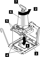
- Close the microprocessor bracket frame.
- Carefully close the microprocessor release lever to the closed position to secure the microprocessor in the socket.
- After alignment, carefully place the microprocessor onto
the socket. Close the microprocessor-bracket frame ( 3 ). Tip: Do not force the microprocessor. The microprocessor fits only one way on the socket.Figure 4. Closing the SAN Volume Controller 2145-DH8 microprocessor-bracket frame
- 1 Microprocessor
- 2 Microprocessor-release lever
- 3 Microprocessor-bracket frame
- Clean the grease from the heat sink and apply new grease
on the microprocessor. When you are installing the heat sink on the same microprocessor that it was removed from, make sure that the following requirements are met:
To replace damaged or contaminated thermal grease on the microprocessor and heat sink, complete the following steps:
- Use the thermal-grease syringe to place nine uniformly spaced dots of 0.02 mL each on the top of
the microprocessor, as shown in Figure 5. The outermost
dots must be within approximately 5 mm of the edge of the microprocessor to ensure uniform
distribution of the grease.Figure 5. Applying thermal grease to the SAN Volume Controller 2145-DH8 microprocessor
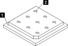
- 1 Microprocessor
- 2 0.02 mL of thermal grease
Note: If properly applied, approximately half of the grease remains in the syringe when you are done.
- Use the thermal-grease syringe to place nine uniformly spaced dots of 0.02 mL each on the top of
the microprocessor, as shown in Figure 5. The outermost
dots must be within approximately 5 mm of the edge of the microprocessor to ensure uniform
distribution of the grease.
- Align the heat sink on top of the microprocessor,
as shown in Figure 6. Figure 6. Installing the heat sink on the SAN Volume Controller 2145-DH8 microprocessor
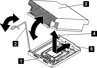
- 1 Microprocessor
- 2 Heat sink release lever
- 3 Heat sink
- 4 Lock tab
- 5 Retainer bracket
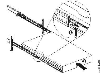
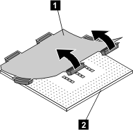
- Lift the locking levers ( 1 in Figure 7) on the slide
rails and push the server 2 all the way
into the rack until it clicks into place. Figure 7. Raising the locking levers of the SAN Volume Controller 2145-DH8 slide rails of the rack