Network configuration planning
As you plan for installing systems in your data center, review information about the network resources and your configuration options.
When you prepare to connect your network to a Cloud Pak System, consider how you will enable connectivity to the user interface (System Management) and enable connections to the virtual machines (IP Group) that are deployed by the system. These network connections are separate entities that ensure system and data security and maintenance.
- VLANs
- System Management: This VLAN type is intended for accessing the console and also to provide a way to send all network traffic outside the rack. You can define only one VLAN with this type for the entire system.
- IP Group: This VLAN type is intended for defining IP
groups. You can define multiple VLANs with this type and you can specify ranges of numbers for the
VLAN IDs.Note: For hardware data plane internal operations, the switching silicon reserves a range of VLANs. The reserved range is
3850-3999for the Top of Rack switches (Mellanox TOR switch SN2410). VLANs from this range cannot be used on the rack.
- Links
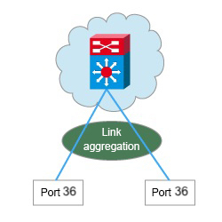
- LACP:The standard-based negotiation protocol, which is known as IEEE 802.1ax Link
Aggregation Control Protocol (LACP), is a way to dynamically build an Etherchannel.Note: Etherchannel type is not supported on IBM® Cloud Pak System W4600 system.
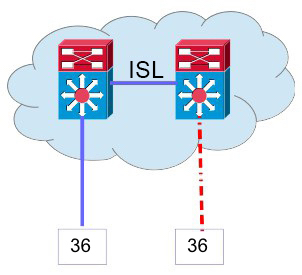
- No aggregation: If aggregation is not possible, this method is available, but not suggested, to provide high availability with no aggregation. With this method, it is suggested to enable PVRST to avoid loops.
- LACP:The standard-based negotiation protocol, which is known as IEEE 802.1ax Link
Aggregation Control Protocol (LACP), is a way to dynamically build an Etherchannel.
Some system functions use an ICMP ping to the management network gateway to confirm connectivity from the system to the network. Therefore, ICMP pings must be enabled on the management network gateway for these functions to work properly.
Concepts and terms for network configuration and administration are further described in Network configuration overview.
Network topologies
The recommended topologies for network configuration are described in the following sections. In each figure, the top switch is part of the external customer network outside of the system.
System Management IP
You can configure the System Management IP network based on one of these
topologies: no aggregation, LACP, and HSRP.

Deployment and communication options for applications
As you are determining your network configurations, consider deployment and communication options for your applications.
Examples a multi-tier solution deployment are illustrated in the following sections. In each figure, the top switch is part of the external customer network outside of the system.
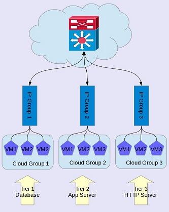
Cloud management by way of internal network
In a three-tier configuration, one cloud group contains all databases, another cloud
group contains the application servers, and a third cloud group contains the HTTP servers. Each tier
uses a separate subnet for IP groups, which provides isolation between the virtual machines that
belong to each cloud group. Communication is allowed by establishing routes from one IP group to
another, and communication is restricted by firewalls established between the IP groups. For more
information, see Firewall requirements for Cloud Pak System patterns. This configuration requires at least three compute nodes (one in each cloud group)
and three IP groups with enough IP addresses to deploy as many virtual machines as needed.
- Configuring subnet routes in the cloud management IP group to the system
- Configuring subnet routes in the cloud management IP group to any other cloud management IP group that will be spanned by the deployment
- Ensuring that your L3 routing and firewall configuration permits communication among these subnets
If your environment contains only two compute nodes, you can achieve a similar configuration by using an external network configuration. Two types of IP groups are needed for each tier: one used for the system to manage the virtual machine and another one used for virtual machine access and communication between the applications. In addition, the system management artifacts require two extra IP addresses in the same subnet to connect to the IP Group <N>a Management.
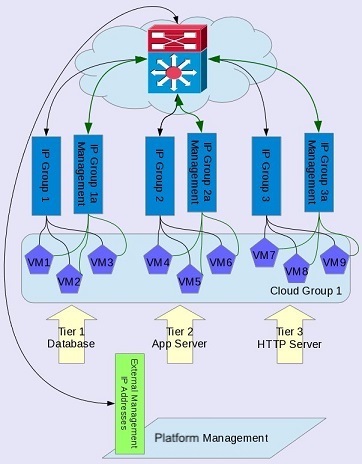
Before you deploy the virtual machines, you must define the routing as follows:
- IP addresses for Cloud Management by way of External Networks < -- > IP Group 1a Management
- IP addresses for Cloud Management by way of External Networks < -- > IP Group 2a Management
- IP addresses for Cloud Management by way of External Networks < -- > IP Group 3a Management
- IP Group 1 < -- > IP Group 2
- IP Group 2 < -- > IP Group 3
For more information, see Firewall requirements for Cloud Pak System patterns.