Lesson 4: Create an application deployment scenario
About this task
- One server is running an application server.
- One server is running a database.
- One server is running an application server and a client for the database.
In this lesson, you create topologies to describe how your application will be deployed on both of these environments, in each case using the same physical model from the previous lesson. Using the same physical model for each deployment instance illustrates how you can model the technology choices in the physical model once and then apply those choices to many deployment instances.
All the units in the infrastructure topologies have a contract of public, rather than public-editable as all of your previous units have. You can see the contract of a unit by double-clicking it and selecting General from the list at the top of the pop-up window:
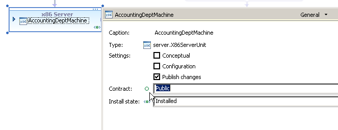
By contrast, the units in the topologies that you create in this lesson have a contract of private. Up to this point in the tutorial, all of the units you created have a contract of public-editable, because the units were at least one level of abstraction above a deployment instance. Thus, any problems or dependencies on the units could be resolved in a later topology by providing other links or units. However, the topologies that you create in this lesson represent specific deployment instances. Therefore, all problems and dependencies must be resolved before you can use the topology as a deployment instance.
Also, all these units are concrete because they represent specific, existing hardware and software. Until now, most of the units that you have worked with are conceptual, for many of the same reasons that they are public-editable.
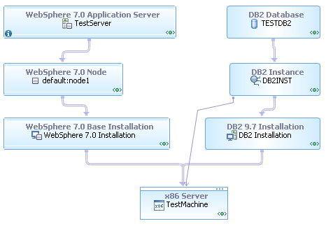
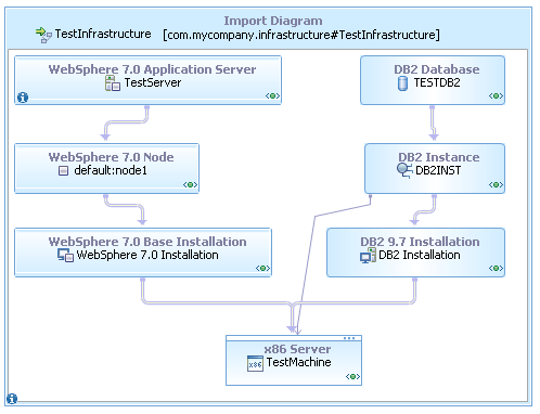
Realizing the physical model to the test infrastructure
Procedure
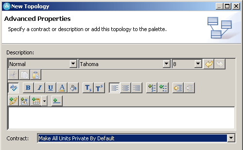
- Create a new topology with a default contract of private:
- Select your project and click .
- In the New Topology window, select the Basic Topologies category and the Blank Topology template.
- Name the new topology TestDeploymentInstance.
- Set the Namespace field to com.mycompany, but do not click Finish yet.
- Click Next.
- On the second page of the New Topology window,
set the Contract field to Make All
Units Private by Default.
- Click Finish.
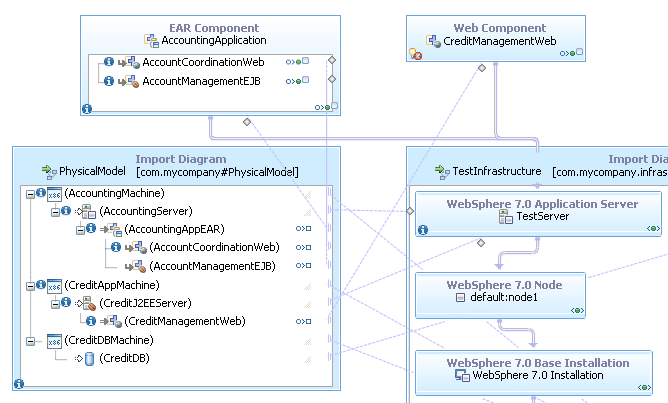
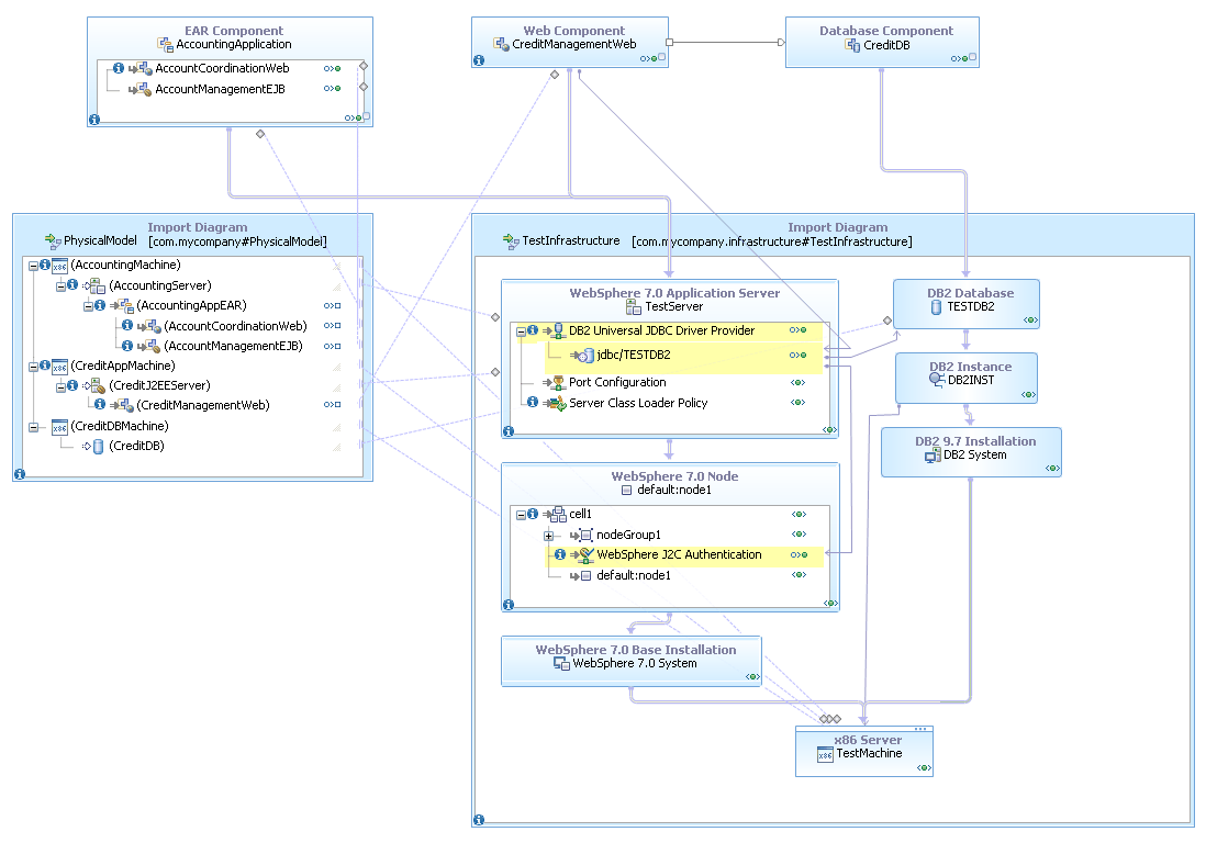
- Convert the imported diagram to a shapes container. You can drag units out of the imported diagram to use them as though they were in the current topology or use them from within the Import Diagram container.
- Expand the servers and applications in the imported diagram.
There are several errors in this imported diagram that did not exist when you were editing the physical model. Because you specified that units in this topology are private by default, the topology editor is stricter about identifying problems that will prevent deployment. For example, many of the units in the imported physical model, such as the server hardware units, have errors that are labeled "Conceptual unit not realized." Because this topology reflects a specific deployment instance, all of the units must be concrete or realized to a concrete unit for the deployment instance to meet all of the requirements set down by the physical model.
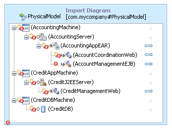
- Create realization links from the three server hardware
units in the physical model (AccountingMachine, CreditAppMachine,
and CreditDBMachine) to the TestMachine unit in the infrastructure
topology. Tip: You can search for valid link targets by dragging the link handle to an empty place on the diagram and selecting a type of link.
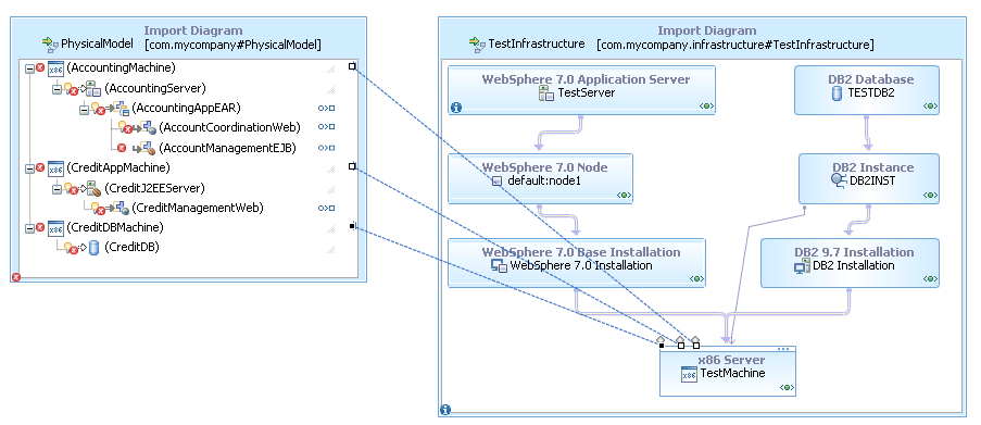
Recall that the server hardware units in the physical model represent specifications for hardware, rather than specific pieces of hardware. In this case, the hardware in the infrastructure model satisfies all of the specifications in each of the conceptual units; therefore, you can use that single piece of hardware in the place of all three conceptual units.
- Create realization links from the CreditJ2EEServer and
AccountingServer units in the logical model to the TestServer server
unit in the infrastructure topology.
The link from AccountingServer to TestServer is valid because the units are of the same type and have the same capabilities. The link from CreditJ2EEServer to TestServer is valid because the target unit is a subtype of the source unit and the target unit has all of the capabilities of the source unit.
The relationship between these two units is an example of how you can describe the needs of the application in the physical model without specifying every detail. In this case, the CreditManagementWeb application needs a Java™ EE-compliant server, but the application does not need the server to be any particular brand of server or to support any particular version of Java. In the deployment instance, you can resolve that generic Java EE-compliant server unit to a specific brand and version of server. In this way, each level of abstraction specifies only the details that are significant at that level.
Results
Importing the application components
About this task
Show me Lesson- Importing the application components
The sample project includes an EAR file (that is, a Java EE application), a WAR file (a web application), and a DDL file (a specification for a group of database tables) in the Resources folder. For the purposes of the tutorial, imagine that this application was sent to you to be deployed as described in the physical model. In this section, you add these application components to the deployment instance and specify how they will be deployed.
Procedure
- In
the Project Explorer view, expand the Resources folder
of your project and drag the CreditDB.ddl file to the diagram. This DDL file describes the database that the application
requires. When you drag the DDL file to the diagram, the topology
editor creates a database unit that corresponds to the file. This
unit is bound to the DDL file in the same way that the components
in the logical model were bound to the UML components.
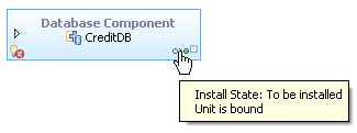
You can tell that this unit is bound by the square icon at the bottom right corner of the unit. The unit also has an install state of To be installed, which indicates that it is not currently installed but needs to be.
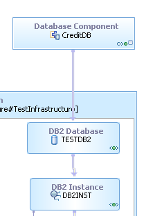
This unit also has an error because it must be hosted on a database.
- Create a hosting link from the database component to the DB2 database unit in the infrastructure
topology.
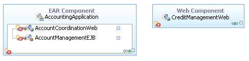
- From the Resources folder of the project,
drag the EAR and WAR files to the diagram, and expand the EAR unit. These units are bound to the application files like the database component is bound to the DDL file. Like the database component, they must be hosted on the infrastructure and used to realize the components in the physical model.
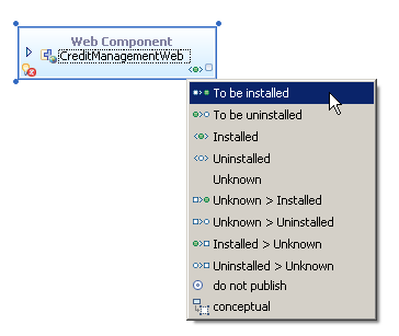
- Set the install state of the web component unit to To
be installed:
- Click the Installed icon at the bottom right corner of the web component.
- From the list of install states, click To be installed.
- Similarly, set the install state of the EJB and web units
inside the EAR unit to To be installed.
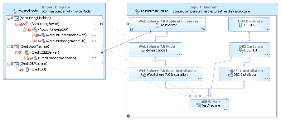
- Create realization links from the EAR, web, and EJB units
in the physical model to the bound units that you just created. Now all of the errors on the physical model are gone.
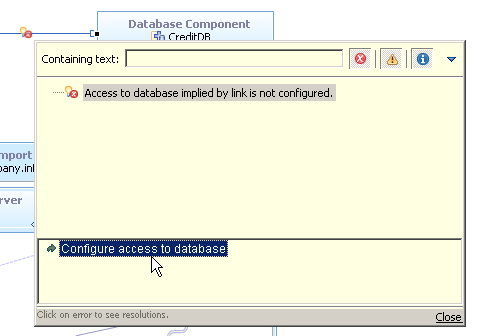
One error remains in the deployment model: the database requirement on the CreditManagementWeb unit is not satisfied:
This error is labeled "Unsatisfied jdbc/CreditDB requirement." When you import the EAR and WAR files, the topology editor examines the applications in the files and adds requirements to the units to match the needs of the applications. This web module has a data source requirement, so the topology editor creates a corresponding requirement on the unit. In the next few steps, you configure the connection between the web module and the database and resolve this error.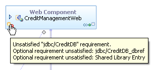
- Create a dependency link from the CreditManagementWeb unit
to the CreditDB database component:
- In the Common Tools drawer of the Palette, click Dependency Link.
- Drag the dependency link from the web unit to the database
component. A window opens showing the possible links
to be created between the units:
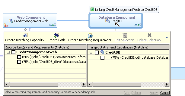
- Select the check box next to the link with the 50% value in the left column. The check box for the corresponding capability on the target unit is selected automatically.
- Click Add, then click Apply.
- Click the error icon on the dependency link, select the
error, and then double-click the resolution that is labeled "Configure
access to database." The topology editor adds three units to the infrastructure model:
 These units are highlighted in yellow because they are not part of the imported diagram, although they appear inside it. The units are in the TestDeploymentInstance topology, but they are shown on their hosts, the units in the infrastructure topology.
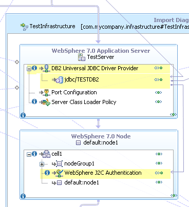
Also, the new units are configuration units, which represent settings that are applied to other units, rather than discrete pieces of software. In this case, the topology editor indicates that a JDBC provider and J2C authentication must be added to the server configuration in order for the application to be able to access the database while running on that server.
Results
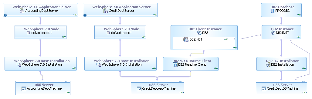
Realizing the physical model to the production infrastructure
About this task
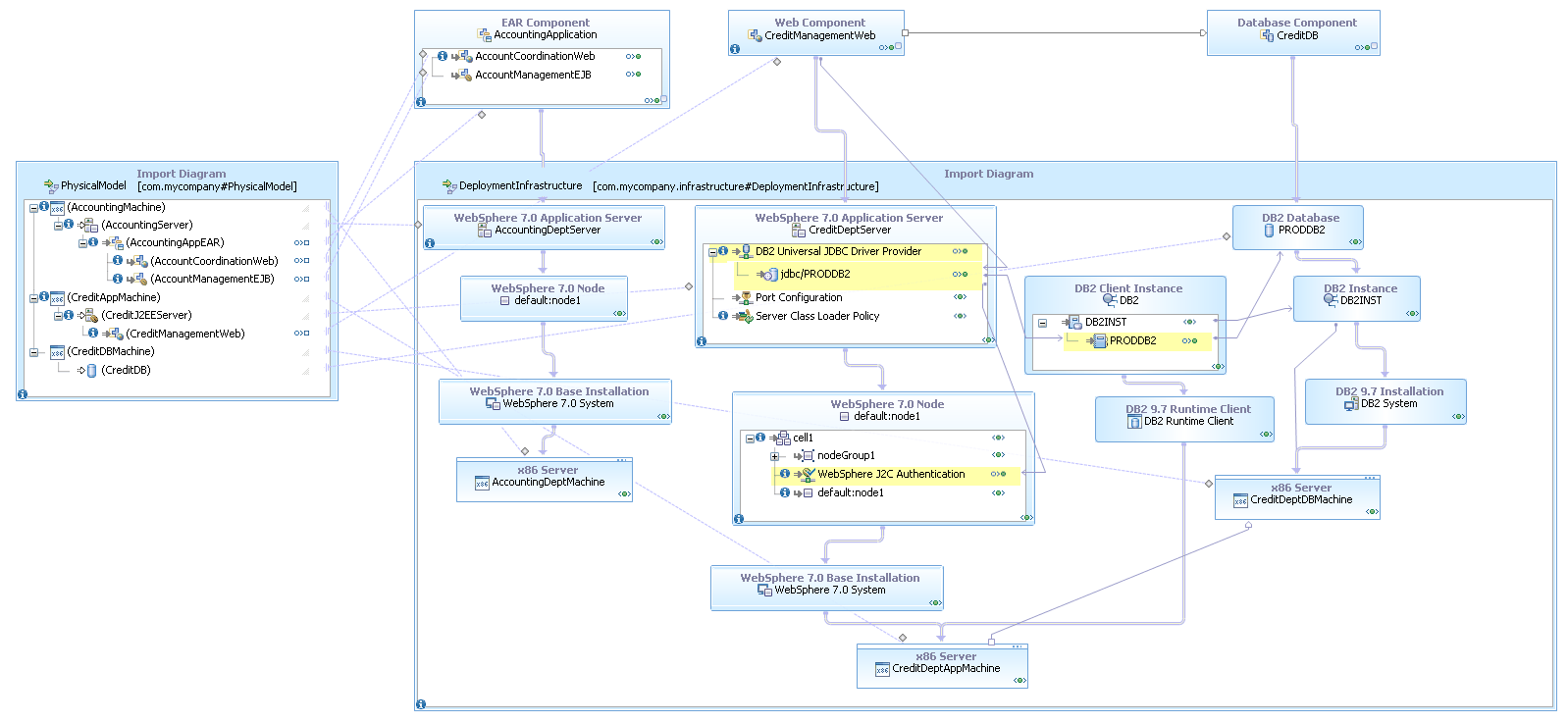
- Create a new topology for the deployment instance. This topology must have a default contract of private.
- Import the deployment infrastructure topology diagram.
- Import the physical model topology diagram.
- Import the EAR, WAR, and DDL files and set their install states.
- Create realization and hosting links.
- Create the dependency link to the database and use the resolution to configure the database connection.
When you are finished, the new topology will look similar to this:
Summary
You can import the completed project for this tutorial into your workspace to check your work. To import this project, see the sample Planning deployment with the topology editor tutorial.