Rack installation specifications for racks that are not purchased from IBM
Learn about the requirements and specifications for installing IBM® systems into racks that were not purchased from IBM.
Learn about the requirements and specifications for 19-inch racks. These requirements and specifications are provided as an aid to help you understand the requirements to install IBM systems into racks. It is your responsibility, working with your rack manufacturer, to ensure that the rack that is chosen meets the requirements and specifications that are listed here. Mechanical drawings of the rack, if available from the manufacturer, are recommended for comparison against the requirements and specifications.
IBM maintenance services and installation planning services do not cover verification of non-IBM racks for compliance to Power Systems rack specifications. IBM offers racks for IBM products that are tested and verified by IBM development labs to comply with applicable safety and regulatory requirements. These racks are also tested and verified to fit and function with IBM products. The customer is responsible for verifying with the rack manufacturer that any non-IBM racks comply with IBM specifications.
Rack specifications
The general rack specifications include the following specifications:
- The rack or cabinet must meet the EIA Standard EIA-310-D for 19-inch racks published August 24, 1992. The EIA-310-D standard specifies internal dimensions, for example, the width of the rack opening (width of the chassis), the width of the module mounting flanges, and the mounting hole spacing.
- The front rack opening must be a minimum of 450 mm (17.72 in.) wide, and the rail-mounting holes
must be 465 mm plus or minus 1.6 mm (18.3 in. plus or minus 0.06 in.) apart on center (horizontal
width between vertical columns of holes on the two front-mounting flanges and on the two
rear-mounting flanges).
Figure 1. Rack specifications (top-down view) 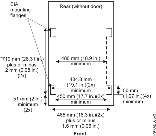
* The range for models 5105-22E, 9008-22L, 9009-22A, 9009-41A, 9009-42A, 9223-22H, and 9223-42H is 609.6 mm - 812.8 mm (24.0 in. - 32.0 in.).
-
The vertical distance between mounting holes must consist of sets of three holes spaced (from bottom to top) 15.9 mm (0.625 in.), 15.9 mm (0.625 in.), and 12.7 mm (0.5 in.) on center (making each three-hole set of vertical hole spacing 44.45 mm (1.75 in.) apart on center).

-
The following rack hole sizes are supported for racks where IBM hardware is mounted:
- 7.1 mm (0.28 in.) plus or minus 0.1 mm (round)
- 9.5 mm (0.37 in.) plus or minus 0.1 mm (square)
The rack or cabinet must be capable of supporting an average load of 20 kg (44 lb) of product weight per EIA unit.
For example, a four EIA drawer has a maximum drawer weight of 80 kg (176 lb).
-
The system requires space at the rear of the rack for system brackets and cables.
For model 5105-22E, 9008-22L, 9009-22A, 9009-41A, 9009-42A, 9223-22H, and 9223-42H, you must have a minimum rear clearance of 240 mm (9.45 in.).
Figure 2. Model 5105-22E, 9008-22L, 9009-22A, 9009-41A, 9009-42A, 9223-22H, and 9223-42H rear rack clearance 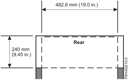
For model 9040-MR9, you must have a minimum rear clearance of 246 mm (9.7 in.) or 280 mm (11.0 in.) depending on the type of rack bracket that is used during installation.
Figure 3. Model 9040-MR9 rear rack clearance 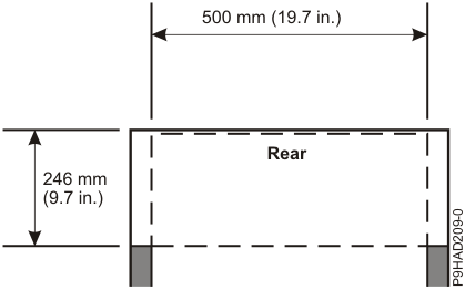
Figure 4. Model 9040-MR9 rear rack clearance 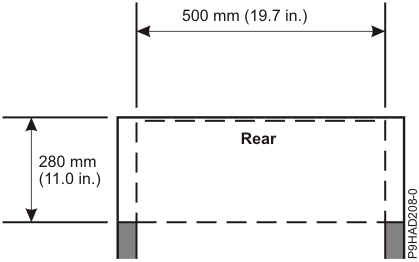
For model 9080-M9S, you must have a minimum rear clearance of 240 mm (9.45 in.) or 280 mm (11.0 in.) depending on the width of the available rack space and the type of rack bracket that is used during installation.
Figure 5. Model 9080-M9S rear rack clearance 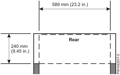
Figure 6. Model 9080-M9S rear rack clearance (narrow rack bracket installation) 
For models 5141-AF8, 5141-FN1, and 5141-FN2, you must have a minimum rear clearance (A) of 558.5 mm (22.0 in.) measured from the rear EIA mounting flange of IBM rack model 7965-S42. For this IBM rack, the distance between front and rear EIA surfaces is 719 mm (28.31 in.). Additionally, you must have a minimum width clearance (B) 482.6 mm (19.0 in.), centered within the rack.
Figure 7. Model 5141-AF8, 5141-FN1, and 5141-FN2 rear rack clearance 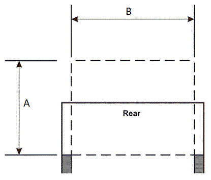
For model 5141-092, you must have a minimum rear clearance (A) of 600.0 mm (23.6 in.) measured from the rear EIA mounting flange of IBM rack model 7965-S42. For this IBM rack, the distance between front and rear EIA surfaces is 719 mm (28.31 in.). Additionally, you must have a minimum width clearance (B) 482.6 mm (19.0 in.), centered within the rack.
Figure 8. Model 5141-092 rear rack clearance 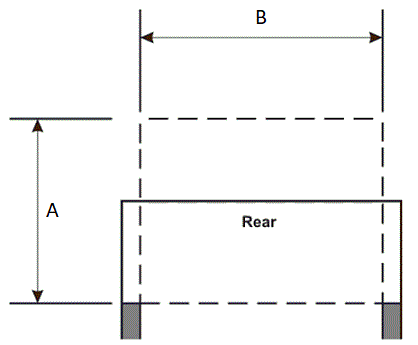
For model 5147-102, you must have a minimum rear clearance (A) of 680 mm (26.7 in.) measured from the rear EIA mounting flange of IBM rack model 7965-S42. For this IBM rack, the distance between front and rear EIA surfaces is 719 mm (28.31 in.). Additionally, you must have a minimum width clearance (B) 475.0 mm (18.7 in.), centered within the rack.
Figure 9. Model 5147-102 rear rack clearance 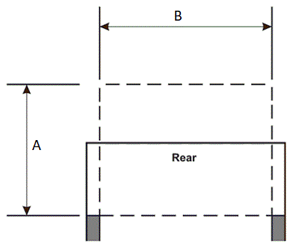
For model 5147-106, you must have a minimum rear clearance of 630 mm (24.8 in.) measured from the rear EIA mounting flange of IBM rack model 7965-S42. For this IBM rack, the distance between front and rear EIA surfaces is 719 mm (28.31 in.). Additionally, you must have a minimum width clearance (B) 482.6 mm (19.0 in.), centered within the rack.
Figure 10. Model 5147-106 rear rack clearance 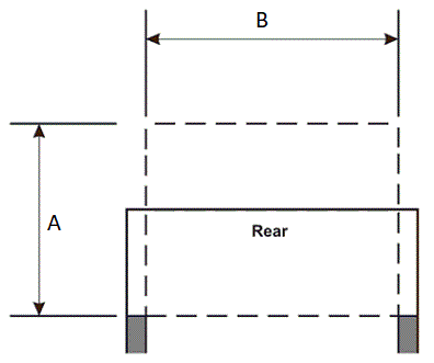
-
Only ac power drawers are supported in the rack or cabinet. It is strongly recommended to use a power distribution unit that meets the same specifications as IBM power distribution units to supply rack power (for example, feature code 7188). Rack or cabinet power distribution devices must meet the drawer voltage, amperage, and power requirements, as well as that of any additional products that are connected to the same power distribution device.
The rack or cabinet power receptacle (power distribution unit, uninterruptible power supply, or multi-outlet strip) must have a compatible plug type for your drawer or device.
- The rack or cabinet must be compatible with the drawer-mounting rails. The rail-mounting
pins and screws must fit securely and snugly into the rack or cabinet rail-mounting holes. The
mounting rails and mounting hardware that are provided with IBM products are designed and tested to safely support the product during
operation and service activities, and to safely support the weight of your drawer or device. The
rails must facilitate service access by allowing the drawer to be safely extended, if necessary,
forward, backward, or both. Some rails, with IBM features for non-IBM racks, provide
drawer-specific anti-tip brackets, rear lock-down brackets, and cable management guides that require
clearance on the rear side of the rails.Note: If the rack or cabinet has square holes on the mounting flanges, an adapter might be required.
- The rack or cabinet must have stabilization feet or brackets installed in the front of the rack,
or have another means of preventing the rack/cabinet from tipping while the drawer or device is
pulled into its extreme front service positions. Note: Examples of some acceptable alternatives: The rack or cabinet might be securely bolted to the floor, ceiling or walls, or to adjacent racks or cabinets in a long and heavy row of racks or cabinets.
- If present, front and rear doors must be able to open far enough to provide unrestrained access for service or be easily removable. If doors must be removed for service, it is the responsibility of the customer to remove them before service.
- Front and rear doors must not violate the previously defined front and rear rack space that is required for the system.
- The rack or cabinet must provide adequate front-to-back ventilation. Note: Rack doors must be fully perforated to provide proper front-to-back airflow for mounted Information Technology (IT) equipment. The total door area must result in a minimum of 45% opening area. Rear doors must not create back pressure that can interfere with the server fan operation.
General safety requirements for IBM products installed in a non-IBM rack or cabinet
The general safety requirements for IBM products that are installed in non-IBM racks are:
- Any product or component that plugs into either an IBM
power distribution unit or mains power (by using a power cord), or uses any voltage over 42 V
ac or 60 V dc (considered to be hazardous voltage) must be Safety Certified by a Nationally
Recognized Test Laboratory (NRTL) for the country in which it is installed.
Some of the items that require safety certification might include the rack or cabinet (if it contains electrical components integral to the rack or cabinet), fan trays, power distribution unit, uninterruptible power supplies, multi-outlet strips, or any other products that are installed in the rack or cabinet that connect to hazardous voltage.
Examples of OSHA-approved NRTLs for the US:- UL
- ETL
- CSA (with CSA NRTL or CSA US mark)
Examples of approved NRTLs for Canada:- UL (Ulc mark)
- ETL (ETLc mark)
- CSA
The European Union requires a CE mark and a Manufacturer's Declaration of Conformity (DOC).
Certified products must have the NRTL logos or marks somewhere on the product or product label. However, proof of certification must be made available to IBM upon request. Proof consists of such items as copies of the NRTL license or certificate, a CB Certificate, a Letter of Authorization to apply the NRTL mark, the first few pages of the NRTL certification report, Listing in an NRTL publication, or a copy of the UL Yellow Card. Proof should contain the manufacturers name, product type, and model, standard to which it was certified, the NRTL name or logo, the NRTL file number or license number, and a list of any Conditions of Acceptance or Deviations. A Manufacturer's Declaration is not proof of certification by an NRTL.
- The rack or cabinet must meet all electrical and mechanical safety legal requirements for the country in which it is installed. The rack or cabinet must be free of exposed hazards (such as voltages over 60 V dc or 42 V ac, energy over 240 VA, sharp edges, mechanical pinch points, or hot surfaces).
- There must be an accessible and unambiguous disconnect device for each product in the rack,
including any power distribution unit.
A disconnect device might consist of either the plug on the power cord (if the power cord is no longer than 1.8 m (6 ft)), the appliance inlet receptacle (if the power cord is of a detachable type), or a power on/off switch, or an Emergency Power Off switch on the rack, provided all power is removed from the rack or product by the disconnect device.
If the rack or cabinet has electrical components (such as fan trays or lights), the rack must have an accessible and unambiguous disconnect device.
- The rack or cabinet, power distribution unit and multi-outlet strips, and products that are
installed in the rack or cabinet must all be properly grounded to the customer facility ground.
There must be no more than 0.1 Ohms between the ground pin of the power distribution unit or rack plug and any touchable metal or conductive surface on the rack and on the products that are installed in the rack. Grounding method must comply with applicable country's electric code (such as NEC or CEC). Ground continuity can be verified by your IBM service personnel, after the installation is completed, and must be verified before the first service activity.
- The voltage rating of the power distribution unit and multi-outlet strips must be compatible
with the products plugged into them.
The power distribution unit or multi-outlet strips current and power ratings are rated at 80% of the building supply circuit (as required by the National Electrical Code and the Canadian Electrical Code). The total load that is connected to the power distribution unit must be less than the rating of the power distribution unit. For example, a power distribution unit with a 30 A connection is rated for a total load of 24 A (30 A x 80 %). Therefore, the sum of all equipment that is connected to the power distribution unit in this example must be lower than the 24 A rating.
If an uninterruptible power supply is installed, it must meet all the electrical safety requirements as described for a power distribution unit (including certification by an NRTL).
- The rack or cabinet, power distribution unit, uninterruptible power supply, multi-outlet
strips, and all products in the rack or cabinet must be installed according to the manufacturer's
instructions, and in accordance with all national, state or province, and local codes and laws.
The rack or cabinet, power distribution unit, uninterruptible power supply, multi-outlet strips, and all products in the rack or cabinet must be used as intended by the manufacturer (per manufacturer's product documentation and marketing literature).
- All documentation for use and installation of the rack or cabinet, power distribution unit, uninterruptible power supply, and all products in the rack or cabinet, including safety information, must be available onsite.
- If there is more than one source of power in the rack cabinet, there must be clearly visible safety labels for Multiple Power Source (in the languages that are required for the country in which the product is installed).
- If the rack or cabinet or any products that are installed in the cabinet had safety or weight labels that are applied by the manufacturer, they must be intact and translated into the languages that are required for the country in which the product is installed.
- If the rack or cabinet has doors, the rack becomes a fire enclosure by definition and must
meet the applicable flammability ratings (V-0 or better). Totally metal enclosures at least 1 mm
(0.04 in.) thick are considered to comply.
Nonenclosure (decorative) materials must have a flammability rating of V-1 or better. If glass is used (such as in rack doors), it must be safety glass. If wood shelves are used in the rack/cabinet, they must be treated with a UL Listed flame-retardant coating.
- The rack or cabinet configuration must comply with all
IBM
requirements for "safe to service" (contact your
IBM
Installation Planning Representative for assistance in determining if the environment is
safe).
There must be no unique maintenance procedures or tools that are required for service.
Elevated service installations, where the products to be serviced are installed between 1.5 m and 3.7 m (5 ft and 12 ft) above the floor, require the availability of an OSHA- and CSA-approved nonconductive step ladder or ladders. If a ladder or ladders are required for service, the customer must supply the OSHA- and CSA- approved nonconductive step ladder (unless other arrangements are made with the local IBM Service Branch Office). Some products can have rack installation limitations. Refer to the specific server or product specifications for any restrictions. Products that are installed over 2.9 m (9 ft) above the floor require a Special Bid to be completed before they can be serviced by IBM service personnel.
For products not intended for rack-mounting to be serviced by IBM, the products and parts that are replaced as part of that service must not weigh over 11.4 kg (25 lb) Contact your Installation Planning Representative if in doubt.
There must not be any special education or training that is required for safe servicing of any of the products that are installed in the racks. Contact your Installation Planning Representative if you are in doubt.