Connecting the 5147-024, ESLL, or ESLS storage enclosure to your system
Learn how to connect the 5147-024, ESLL, or ESLS storage enclosure to your system.
Note: The cables that are used to connect the 5147-024, ESLL, or ESLS storage enclosure to a server are different from the
cables that are used with the 5887 disk drive enclosure.
To connect the 5147-024, ESLL, or ESLS storage enclosure to a system with support for a
serial-attached SCSI (SAS) storage enclosure, complete the following steps.For more information about SAS cabling and cabling configurations, see Serial-attached SCSI cable planning.
- Ensure that you have the electrostatic discharge (ESD) wrist strap attached. If not, attach it now.
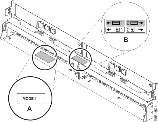
- Confirm the factory-set
mode of the enclosure by using information that is printed on stickers
at the rear of the enclosure. Stickers are attached to the lower-left
shelf of the chassis (A) and the center support
between the enclosure services manager modules (B).
The stickers indicate whether the enclosure is set to mode 1, mode
2, or mode 4. For
more information, see Figure 1.Note: The 5147-024 storage enclosure only supports mode 1.Figure 1. Mode sticker locations at the rear of the 5147-024, ESLL, or ESLS storage enclosure
- Ensure that all adapters that you need to connect to the 5147-024, ESLL, or ESLS storage enclosure are installed in the system or expansion unit. If the adapters are not installed, complete the adapter installation procedure for your system or expansion unit before you continue with this task. For instructions, see PCIe adapters.
- If the system requires an internal cable
to be installed to produce an external SAS port for connection with
the enclosure, confirm that the installation was completed.Remember: When you install or confirm the use of an external SAS port, record the location of the external SAS port on the system. Later in this procedure, you are instructed to install the external SAS cable to this system connector location.
- Determine the configuration that you will use to
cable the SAS adapter to the 5147-024, ESLL, or ESLS storage enclosure.
The following list shows some of the common connections, but not all possible connection options.
For more configuration options, see Planning for serial-attached SCSI cables.Notes:
- The 5147-024 storage enclosure attaches to your system with AA12 cables (or other straight cables).
- The ESLL or ESLS storage enclosure attaches to your system with YO12 or X12 cables.
- If you use a YO12 cable to attach the ESLL or ESLS storage enclosure to the rear SAS ports of the system model 8247-21L, 8247-22L, 8247-42L, 8284-21A, 8284-22A, 8286-41A, or 8286-42A, the SAS YO12 cable must not exceed the maximum supported length of 3 m (9.8 ft).
- If you are working on a 5147-024, use a mode 1 connection by using two AA12 or other straight cables to two SAS adapters.
- A mode 1 connection of one ESLL or ESLS storage enclosure by using a YO12 cable to a single SAS adapter.
- A mode 1 connection of two ELLL or ESLS storage enclosures by using a YO12 cables to a single SAS adapter.
- A mode 1 connection of one ESLL or ESLS storage enclosure by using a YO12 cables to a SAS adapter pair.
- A mode 1 connection of two ELLL or ESLS storage enclosures by using a YO12 cables to a SAS adapter pair.
- A mode 2 connection of one ESLL or ESLS storage enclosure by using a YO12 cables to two independent SAS adapters.
- A mode 2 connection of one ESLS storage enclosure by using X12 cables to two SAS adapter pairs.
- A mode 4 connection of one ESLL or ESLS storage enclosure by using X12 cables to four independent SAS adapters.
- Locate the connection for each adapter for which you are using an external SAS cable to connect the enclosure. Adapter cables attach to ports at the rear of the systems in which the adapters are installed. To identify the SAS port location for the system in your configuration, see Connector locations and select the appropriate model.
- Select from the following options:
- If the server or expansion unit that you are attaching your 5147-024, ESLL, or ESLS storage enclosure to is powered off, continue with step 12.
- If the system is powered on, you must
do one of the following actions, depending on the supported functions
of your operating system:
- Unconfigure the adapters to which you are connecting the enclosure.
- Power off the adapters to which you are connecting the enclosure.
- Power off the logical partitions or systems that own the adapters to which you are connecting the enclosure.
To do one of these required actions, continue with step 8.
- Do the following conditions apply
to your situation?
- Your system model does not support slot power control.
- Your adapters are not in an I/O enclosure that supports slot power control.
- You are unable to tolerate a temporary
loss of access to other disk devices that might exist on the same
adapters.
- Yes: Power off the system or the logical partitions that own the adapters by completing the steps in Stopping a system or logical partition. Then, continue with step 12.
- No: Continue with step 9.
- Select from the following options:
- To unconfigure the SAS adapters, complete
these steps:
- Unconfigure the SAS adapters.
- Ensure that you have the electrostatic discharge (ESD) wrist strap attached. If not, attach it now.
- Connect the SAS cables from the enclosure to the SAS adapters.
- Reconfigure the SAS adapters.
- Continue with step 12.
- To power off the SAS adapters, complete
these steps:
- Power off the SAS adapters.
- Ensure that you have the electrostatic discharge (ESD) wrist strap attached. If not, attach it now.
- Connect the SAS cables from the enclosure to the SAS adapters.
- Power on the SAS adapters.
- Configure the SAS adapters and devices.
- Continue with step 12.
- Choose one of the following options to cable the SAS adapter:Note: The configuration figures show the use of SAS adapters to represent the external server or expansion unit connections. The adapter can represent one of the following connection types:Note: Adapters are cabled to the enclosure by using ports at the rear of the enclosure. To learn about the enclosure ports that are used in the following options, see Connector locations.
- To complete a mode 1 connection of one 5147-024 storage enclosure by using two AA12 or other straight cables to two adapters in a 5148-22L system, continue with step 13.
- To complete a mode 1 connection of one ESLL or ESLS storage enclosure by using a YO12 cable to a single FC EJ0J or FC EJ0M SAS adapter, go to step 14.
- To complete a mode 1 connection of two ESLL and ESLS storage enclosures by using a YO12 cables to a single FC EJ0J or FC EJ0M SAS adapter, go to step 15.
- To complete a mode 1 connection of one ESLL or ESLS storage enclosure by using a YO12 cables to an FC EJ0L SAS adapter pair or an FC EJ14 SAS adapter pair, go to step 16.
- To complete a mode 1 connection of two ESLL and ESLS storage enclosures by using a YO12 cables to an EJ0L SAS adapter pair or an FC EJ14 SAS adapter pair, go to step 17.
- To complete a mode 2 connection of one ESLL or ESLS storage enclosure by using a YO12 cables to two independent FC EJ0J or FC EJ0M SAS adapters, go to step 18.
- To complete a mode 2 connection of one ESLS storage enclosure by using X12 cables to two FC EJ0L SAS adapter pairs or two FC EJ14 pairs, go to step 19.
- To complete a mode 4 connection of one ESLL or ESLS storage enclosure by using X12 cables to four independent FC EJ0J or FC EJ0M SAS adapters, go to step 20.
If your SAS configuration requirements are not supported by any of these options, go to step 21.
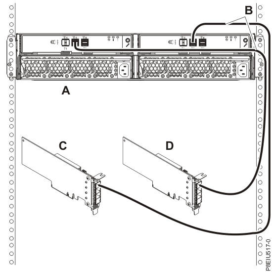
- Complete a mode 1 connection of one 5147-024 storage enclosure (A) by using two
AA12 or other straight cables (B) to two adapters (C,
D), as shown in Figure 2, and then
continue with Connecting cables, power cords, and installing covers.Figure 2. Mode 1 connection of one 5147-024 enclosure by using two AA12 or other straight cables to two adapters
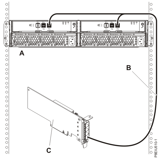
- Complete a mode 1 connection of one enclosure (A) by
using a Y012 cable (B) to a single FC EJ0J or FC EJ0M SAS adapter
(C), as shown in Figure 3, then
continue with Connecting cables, power cords, and installing covers.Note: The single FC EJ0J or FC EJ0M SAS adapter (C) has access to all 12 or 24 drive bays.Figure 3. Mode 1 connection of one ESLL or ESLS storage enclosure by using a YO12 cable to a single FC EJ0J or FC EJ0M SAS adapter
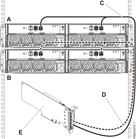
- Complete a mode 1 connection of two enclosures (A and
B) by using YO12 cables (C and D) to a single FC EJ0J or FC EJ0M
SAS adapter (E), as shown in Figure 4, and then continue with Connecting cables, power cords, and installing covers.Note: The single SAS adapter (E) has access to all 24 or 48 drive bays.Figure 4. Mode 1 connection of two ESLL and ESLS storage enclosures by using YO12 cables to a single FC EJ0J or FC EJ0M SAS adapter
- Complete a mode 1 connection of one enclosure
(A) by using YO12 cables (B) to an FC EJ0L SAS adapter
pair or an FC EJ14 SAS adapter pair (C) with adapter-to-adapter (AA) cables
(D), as shown in Figure 5,
and then continue with Connecting cables, power cords, and installing covers.Notes:
- Each adapter in the SAS adapter pair (C) has access to the other adapter and to all 12 or 24 drive bays.
- For SAS adapter pairs, you must attach the cables to the same port on both adapters.
- Both short legs of the cables must attach to the same side of the enclosure and both long legs of the cable must attach to the other side of the enclosure.
Figure 5. Mode 1 connection of one ESLL or ESLS storage enclosure by using YO12 cables to an FC EJ0L SAS adapter pair or an FC EJ14 SAS adapter pair with AA cables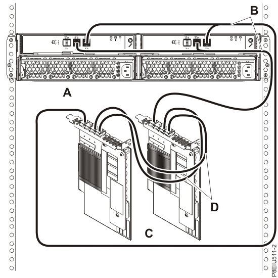
- Complete a mode 1 connection of two enclosures
(A and B) by using YO12 cables (C and D) to an FC
EJ0L SAS adapter pair or an FC EJ14 SAS adapter pair (E) with AA cables
(F), as shown in Figure 6, and then continue with Connecting cables, power cords, and installing covers.Notes:
- Each adapter in the SAS adapter pair (C) has access to the other adapter and to all 24 or 48 drive bays.
- For SAS adapter pairs, you must attach the cables to the same port on both adapters.
- Both short legs of the cables must attach to the same side of the enclosure and both long legs of the cable must attach to the other side of the enclosure.
Figure 6. Mode 1 connection of two ESLL and ESLS storage enclosures by using YO12 cables to an FC EJ0L SAS adapter pair or an FC EJ14 SAS adapter pair with AA cables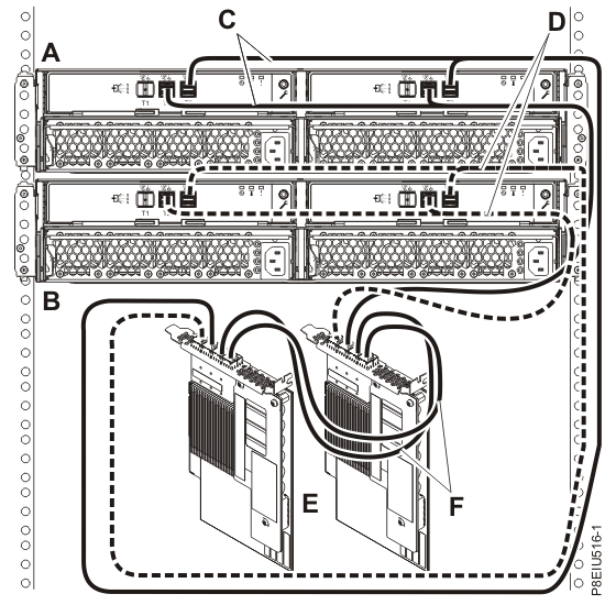
- Complete a mode 2 connection of one enclosure
(A) by using YO12 cables (B) to two independent FC
EJ0J or FC EJ0M SAS adapters, as shown in Figure 7, and then continue with Connecting cables, power cords, and installing covers.Notes:
- Independent SAS adapter 1 (C) does not have access to the other independent adapter and has access only to drive bays D1 - D12.
- Independent SAS adapter 2 (D) does not have access to the other independent adapter and has access only to drive bays D13 - D24.
Figure 7. Mode 2 connection of one ESLL or ESLS storage enclosure by using YO12 cables to two independent FC EJ0J or FC EJ0M SAS adapters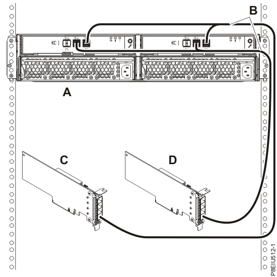
- Complete a mode 2 connection of one enclosure
(A) by using X12 cables (B) to two FC EJ0L SAS adapter
pairs or two FC EJ14 SAS adapter pairs (C, D) with AA cables
(E), as shown in Figure 8,
and then continue with Connecting cables, power cords, and installing covers.Notes:
- Each adapter in the SAS adapter pair 1 (C) has access to the other adapter in pair 1 and to drive bays D1 - D12.
- Each adapter in the SAS adapter pair 2 (D) has access to the other adapter in pair 2 and to drive bays D13 - D24.
- For SAS adapter pairs, you must attach the cables to the same port on both adapters.
- Both short legs of the cables must attach to the same side of the enclosure and both long legs of the cable must attach to the other side of the enclosure.
Figure 8. Mode 2 connection of one ESLS by using X12 cables to two FC EJ0L SAS adapter pairs or two FC EJ14 SAS adapter pairs with AA cables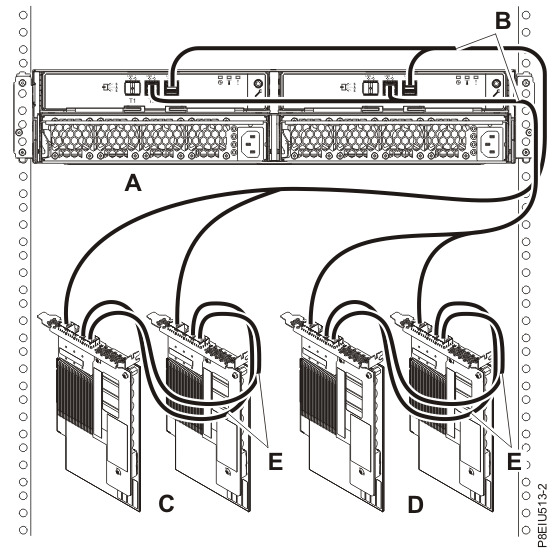
- Complete a mode 4 connection of one enclosure
(A) by using X12 cables (B) to four independent FC
EJ0J or FC EJ0M SAS adapters, as shown in Figure 9, and then continue with Connecting cables, power cords, and installing covers.Note: Refer to Figure 10 for label examples of these cable identifiers.
- The cable that plugs into independent SAS adapter 1 (C) contains a label with the P1 identifier (G). This adapter does not have access to any other independent adapter and has access only to drive bays D1 - D6 (D1 - D3 for the ESLL).
- The cable that plugs into independent SAS adapter 2 (D) contains a label with the P2 identifier (G). This adapter does not have access to any other independent adapter and has access only to drive bays D7 - D12 (D4 - D6 for the ESLL).
- The cable that plugs into independent SAS adapter 3 (E) contains a label with the P1 identifier (G). This adapter does not have access to any other independent adapter and has access only to drive bays D13 - D18 (D7 - D9 for the ESLL).
- The cable that plugs into independent SAS adapter 4 (F) contains a label with the P2 identifier (G). This adapter does not have access to any other independent adapter and has access only to drive bays D19 - D24 (D10 - D12 for the ESLL).
Note: Partial mode 4 configurations are supported with less than 4 adapters leaving an adapter end of the X12 cable not connected.Figure 9. Mode 4 connection of one ESLL or ESLS storage enclosure by using X12 cables to four independent FC EJ0J or FC EJ0M SAS adapters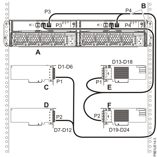 Figure 10. Labels for SAS adapter cables that show P1 and P2 identifiers
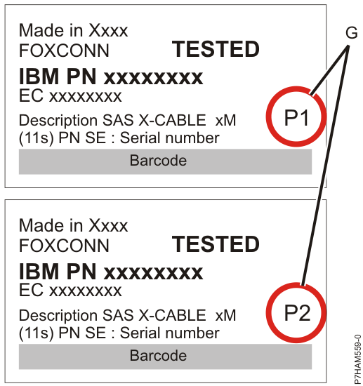
- For more information about SAS cabling and cabling configurations, see Serial-attached SCSI cable planning.