Installing the cable-management arm and connecting and routing power cables
The cable-management arm is used to efficiently route cables so that you have proper access to the rear of the system. After you have installed the cable-management arm, connect and route power cables.
About this task
Note: If you are installing more than one system at this time, install the cable-management arm
after you have installed the other systems into the rack.
Procedure
- Ensure that you have the following parts.
A Support arm B Cable-management stop bracket C Mounting bracket D Cable-management arm E Extension bracket Figure 1. Relative positions of the parts of the cable-management arm before assembly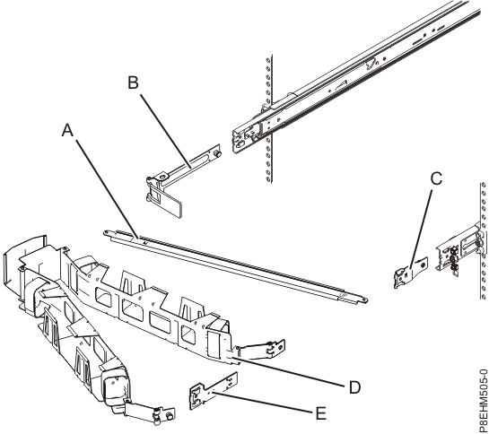
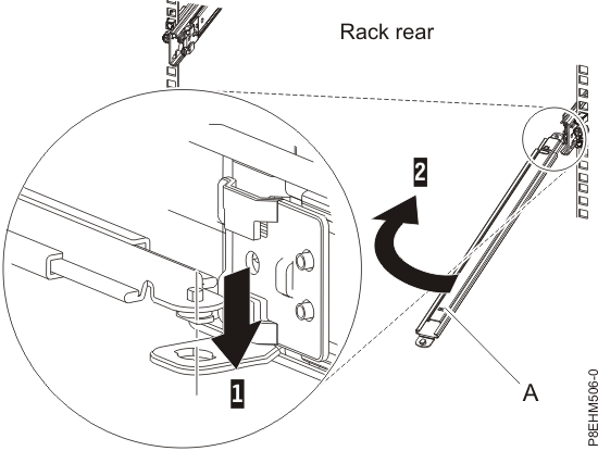
- Connect one end of the support arm (A) to the right slide rail
(1) so that you can swing the other end of the support arm toward the left
side of the rack (2). Note: The support arm (A) is labeled UP and DOWN. Ensure that the side labeled UP is facing upward and to the right.Figure 2. Connecting the support arm
- Locate the hole at the bottom inside corner of the L-shaped
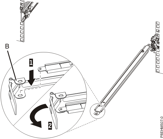
cable-management stop bracket (B). Position the unattached end of the support
arm so that the locking tab on the underside of its tip aligns with the bracket hole. Insert the tab
into the hole (1) and turn the bracket (2) to secure
it to the support arm. For details, see Figure 3. Figure 3. Securing the cable-management stop bracket to the support arm
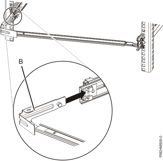
- Attach the cable-management stop bracket (B) to
the slot on the inside of the left slide by sliding the stop bracket (B) into
the slide rail until the spring-loaded pin snaps into place. Figure 4. Installing the mounting bracket into the slide rail
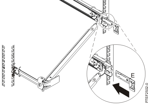
- Slide the extension bracket (E) into
the right slide rail until the spring-loaded pin snaps into place. For details, see Figure 5. Figure 5. Installing the extension bracket into the slide rail
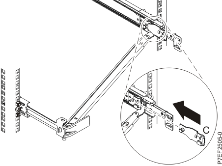
- Attach the mounting bracket (C) to the slot on the inside of the right slide by sliding
the mounting bracket (C) into the slide rail until the spring-loaded pin snaps into place.
For details, see Figure 6. Figure 6. Installing the mounting bracket into the slide rail
- Place the cable-management arm (D) on
the support arm (A). Slide the first cable-management
arm tab into the slot on the mounting bracket (C).
Push the tab until the spring-loaded latch snaps into place. Slide
the other cable-management arm tab into the extension bracket (E) on
the outside of the right slide rail (2). Push
the tab until the spring-loaded latch snaps into place. For details, see Figure 7 and Figure 8. Figure 7. Sliding the cable-management arm tab into the mounting bracket slot
 Figure 8. Sliding the other cable-management arm tab into the extension bracket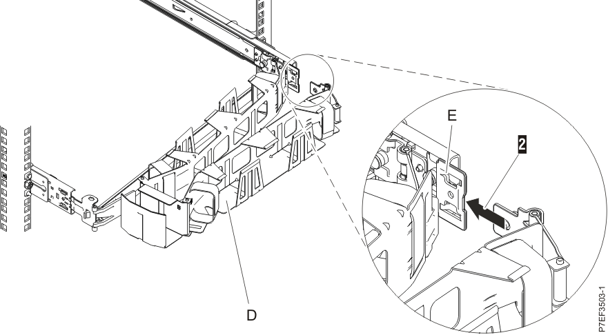
- To connect the power cables, complete the following steps:
- Plug the power cords into the power supplies.
- Route the power cords and other cables on the cable-management arm.
- Attach all cables to the rear of the server. Figure 9. Rear view of the system with ports displayed
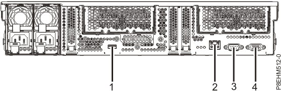
Table 1. Port callouts Identifier Description 1 USB 3.0 2 Ethernet 3 Intelligent Platform Management Interface (IPMI) 4 Video Graphics Array (VGA). Text based capability is only supported at this time. - Plug the system power cords and the power cords for any other attached devices into the alternating current (ac) power source.
