Technical Blog Post
Abstract
Simulating Default Chassis Ping Failure
Body
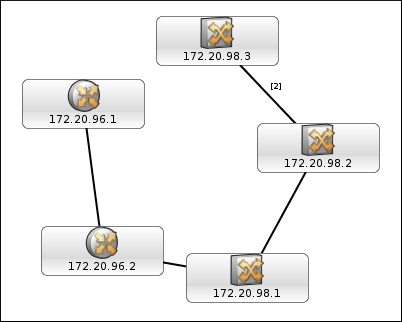
We begin with the following Layer 2 network topology, which is the result of discovering five network devices using SNMP. Initially, there are no events associated with these devices as the devices can be reached by the ncp_poller, i.e. the Default Chassis Ping poll policy always succeeds for these devices.
To simulate ping failure, we can block ping packets from reaching some of the above devices. If ITNM is running on a Linux machine, we can use iptables to achieve this.
The default firewall that comes with a Linux host is the iptables software. In the initial stage, iptables allows all packets to come in and go out of the machine. To verify this, issue the following command (you have to be root to use iptables):
iptables -L -n -v
A sample output is the following:
Chain INPUT (policy ACCEPT 27798 packets, 8233K bytes) pkts bytes target prot opt in out source destination Chain FORWARD (policy ACCEPT 0 packets, 0 bytes) pkts bytes target prot opt in out source destination Chain OUTPUT (policy ACCEPT 27120 packets, 8354K bytes) pkts bytes target prot opt in out source destination
There are three chains in the above output. We are interested in the last chain, i.e. OUTPUT, which is responsible for allowing packets to go out of the Linux machine. In the above, the default policy of the OUTPUT chain is ACCEPT, which is to allow all packets to go out of the box.
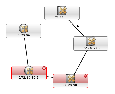
We can now block ping packets from going to selected destination hosts, e.g. 172.20.96.2 and 172.20.98.1. This will simulate ping failure for these two hosts. To achieve this, enter the following commands, which will insert two rules into the OUTPUT chain of iptables, which in turn will block ping packets from going to these hosts:
iptables -A OUTPUT --dest 172.20.96.2 -j DROP iptables -A OUTPUT --dest 172.20.98.1 -j DROP
The output of iptables -L -n -v will now be something like the following:
Chain INPUT (policy ACCEPT 36596 packets, 11M bytes) pkts bytes target prot opt in out source destination Chain FORWARD (policy ACCEPT 0 packets, 0 bytes) pkts bytes target prot opt in out source destination Chain OUTPUT (policy ACCEPT 35790 packets, 11M bytes) pkts bytes target prot opt in out source destination 2 120 DROP all -- * * 0.0.0.0/0 172.20.96.2 1 60 DROP all -- * * 0.0.0.0/0 172.20.98.1
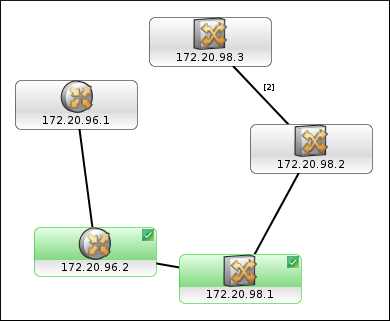
To restore the outage, delete the two rules in the OUTPUT chain of iptables by simply flushing the chain (since there are no other rules available in the chain):
iptables -F OUTPUT
The chains will go back to where they were initially:
Chain INPUT (policy ACCEPT 48980 packets, 15M bytes) pkts bytes target prot opt in out source destination Chain FORWARD (policy ACCEPT 0 packets, 0 bytes) pkts bytes target prot opt in out source destination Chain OUTPUT (policy ACCEPT 48004 packets, 15M bytes) pkts bytes target prot opt in out source destination
UID
ibm11082037